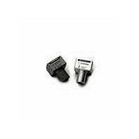
HFBR-2505A Avago Technologies US Inc., HFBR-2505A Datasheet - Page 4

HFBR-2505A
Manufacturer Part Number
HFBR-2505A
Description
RCVR MOD FIBER OPTIC SERCOS SMA
Manufacturer
Avago Technologies US Inc.
Datasheet
1.HFBR-2505A.pdf
(11 pages)
Specifications of HFBR-2505A
Data Rate
10MBd
Voltage - Supply
4.75 V ~ 5.25 V
Current - Supply
27mA
Applications
General Purpose
Function
Fiber Optic Receivers for Sercos applications
Product
Receiver
Wavelength
650 nm
Diode Capacitance
60 pF
Maximum Rise Time
30 ns
Maximum Fall Time
30 ns
Maximum Output Current
16 mA
Operating Supply Voltage
- 0.5 V to + 5.5 V
Maximum Operating Temperature
+ 85 C
Minimum Operating Temperature
- 40 C
Package / Case
PDIP-6
For Use With
Hard Clad Silica
Lead Free Status / RoHS Status
Lead free / RoHS Compliant
Power - Minimum Receivable
-
Lead Free Status / RoHS Status
Lead free / RoHS Compliant, Lead free / RoHS Compliant
Figure 1. Typical forward voltage vs. drive
current.
4
Peak Output Power
0˚C to +70˚C unless otherwise noted.
Notes:
11. Output power with 200 m hard clad silica optical fiber assumes a typical –10.5 dB difference compared to 1 mm plastic optical fiber.
10. Pins 1 and 4 are for mounting and retaining purposes, but are electrically connected; pins 5 and 6 are electrically isolated. It is recommended that
1. Typical data at 25˚C.
2. Optical power measured at the end of 0.5 meters of 1 mm diameter plastic optical fiber with a large area detector.
3. Minimum and maximum values for P
4. Thermal resistance is measured with the transmitter coupled to a connector assembly and fiber, and mounted on a printed circuit board.
5. To further reduce the thermal resistance, the cathode trace should be made as large as is consistent with good RF circuit design.
6. For I
7. 1.6 mm below seating plane.
8. Minimum peak output power at 25˚C is –5.3 dBm (POF) and –16.0 dBm (HCS
9. Optical power measured at the end of 1 meter of 1 mm diameter plastic or 200 m hard clad silica optical fiber with a large area detector.
Model Number
HFBR-1505A
SERCOS
HFBR-1515B
PROFIBUS
HFBR-1505C
INTERBUS-S
2.5
2.3
2.1
1.9
1.7
1.5
I
F,DO
compensation which reduces the variation in P
pins 1, 4, 5, and 6 all be connected to ground to reduce coupling of electrical noise.
1
F,PK
– TRANSMITTER DRIVE CURRENT – mA
> 60 mA, the duty factor must maintain I
10
-40 °C
25 °C
70 °C
0 °C
85 °C
Symbol
P
T
T
over temperature are based on a fixed drive current. The recommended drive circuit has temperature
100
T
Figure 2. Typical normalized optical power vs.
drive current.
over temperature, refer to Figures 4 and 6.
F,AVG
–10.5
–18.0
–10.5
–18.0
–16.9
Min.
I
-10
-20
-30
-40
–7.5
–7.5
–6.2
F,DO
10
0
1
60 mA and pulse width 1 s.
– TRANSMITTER DRIVE CURRENT – mA
Max.
–5.5
–3.5
–5.5
–3.5
–8.5
–8.5
–10
0.0
10
-40 °C
25 °C
®
) for 1505C series only.
dBm
Unit
85 °C
POF, I
POF, I
HCS
POF, I
POF, I
HCS
POF, I
HCS
100
®
®
®
F, dc
F, dc
F, dc
F, dc
F, dc
, I
, I
, I
F, dc
F, dc
F, dc
Figure 3. Typical normalized optical spectra.
Condition
= 35 mA
= 60 mA
= 35 mA
= 60 mA
= 60 mA
1.4
1.2
1.0
0.8
0.6
0.4
0.2
= 60 mA
= 60 mA
= 60 mA
0
610
630
WAVELENGTH – nm
650
-40 °C
Notes 2,3,11
Notes 2,3,11
Notes 3,8,9
Reference
0 °C
Figure 2
Figure 2
Figure 2
25 °C
70 °C
85 °C
670
690


