HFBR-772BWZ Avago Technologies US Inc., HFBR-772BWZ Datasheet - Page 2
HFBR-772BWZ
Manufacturer Part Number
HFBR-772BWZ
Description
XMITTER FO 12X2.7GBD
Manufacturer
Avago Technologies US Inc.
Specifications of HFBR-772BWZ
Wavelength
850nm
Spectral Bandwidth
0.4nm
Capacitance
0.1µF
Connector Type
MTP® (MPO)
Data Rate Max
2.7Gbps
Data Transmission Distance
600m
Supply Current
320mA
Operating Temperature Range
0°C To +80°C
Peak Wavelength
850nm
Supply Voltage Range
3.135V To 3.465V
Lead Free Status / RoHS Status
Lead free / RoHS Compliant
Current - Dc Forward (if)
-
Voltage - Forward (vf) Typ
-
Voltage - Dc Reverse (vr) (max)
-
Lead Free Status / RoHS Status
Lead free / RoHS Compliant, Lead free / RoHS Compliant
Available stocks
Company
Part Number
Manufacturer
Quantity
Price

Part Number:
HFBR-772BWZ
Manufacturer:
AVAGO/安华高
Quantity:
20 000


Design Summary:
Design for low-cost, high-volume manufacturing
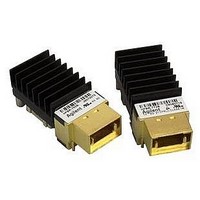
Avago Technologies’ parallel optics solution combines
twelve 2.7 Gbd channels into discrete transmitter and
receiver modules providing a maximum aggregate data
rate of 32 Gb/s. Moreover, these modules employ a heat
sink for thermal management when used on high-density
cards, have excellent EMI performance, and interface with
the industry standard MTP®/MPO connector systems. They
provide the most cost-effective high- density (Gbd per
inch) solutions for high-data capacity applications. See
Figure 1 for the transmitter and Figure 2 for the receiver
block diagrams.
The HFBR-772B transmitter and the HFBR-782B receiver
modules provide very closely spaced, high-speed parallel
data channels. Within these modules there will be some
level of cross talk between channels. The cross talk within
the modules will be exhibited as additional data jitter or
sensitivity reduction compared to single-channel
performance. Avago Technologies’ jitter and sensitivity
specifications include cross talk penalties and thus
represent real, achievable module performance.
Functional Description, Transmitter Section
The transmitter section, Figure 1, uses a 12-channel 850
nm VCSEL array as the optical source and a diffractive
optical lens array to launch the beam of light into the
fiber. The package and connector system are designed
to allow repeatable coupling into standard 12-fiber ribbon
cable. In addition, this module has been designed to be
compliant with IEC 60825 Class 1 eye safety
requirements.
The optical output is controlled by a custom IC, which
provides proper laser drive parameters and monitors drive
current to ensure eye safety. An EEPROM and state
machine are programmed to provide both ac and dc
current drive to the laser to ensure correct modulation,
eye diagram and extinction ratio over variations of
temperature and power supply voltages.
2
Functional Description, ReceiverSection
The receiver section, Figure 2, contains a 12-channel
AlGaAs/ GaAs photodetector array, transimpedance
preamplifier, filter, gain stages to amplify and buffer the
signal, and a quantizer to shape the signal.
The Signal Detect function is designed to sense the proper
optical output signal on each of the 12 channels. If loss
of signal is detected on an individual channel, that channel
output is squelched.
Packaging
The flexible electronic subassembly was designed to
allow high-volume assembly and test of the VCSEL, PIN
photo diode and supporting electronics prior to final
assembly.
Regulatory Compliance
The overall equipment design into which the parallel
optics module is mounted will determine the certification
level. The module performance is offered as a figure of
merit to assist the designer in considering their use in
the equipment design.
Organization Recognition
See the Regulatory Compliance Table for a listing of the
standards, standards associations and testing laboratories
applicable to this product.
Electrostatic Discharge (ESD)
There are two design cases in which immunity to ESD
damage is important.
The first case is during handling of the module prior to
mounting it on the circuit board. It is important to use
normal ESD handling precautions for ESD sensitive
devices. These precautions include using grounded wrist
straps, work benches, and floor mats in ESD controlled
areas.
The second case to consider is static discharges to the
exterior of the equipment chassis containing the module
parts. To the extent that the MTP® (MPO) connector
receptacle is exposed to the outside of the equipment
chassis it may be subject to system level ESD test criteria
that the equipment is intended to meet.
See the Regulatory Compliance Table for further details.
Related parts for HFBR-772BWZ
Image
Part Number
Description
Manufacturer
Datasheet
Request
R

Part Number:
Description:
RECEIVER FIBER OPTIC 600NM 5MBD
Manufacturer:
Avago Technologies US Inc.
Datasheet:

Part Number:
Description:
RECEIVER FIBER OPTIC 600NM 40KBD
Manufacturer:
Avago Technologies US Inc.
Datasheet:

Part Number:
Description:
RCVR FIBER OPTIC INTERBUS-S
Manufacturer:
Avago Technologies US Inc.
Datasheet:

Part Number:
Description:
RCVR OPT HI PERF VERS LINK HORZ
Manufacturer:
Avago Technologies US Inc.
Datasheet:
Part Number:
Description:
RCVR OPT HI PERF VERS LINK HORZ
Manufacturer:
Avago Technologies US Inc.
Datasheet:

Part Number:
Description:
XMITTER FIBER OPTIC 600NM 5MBD
Manufacturer:
Avago Technologies US Inc.
Datasheet:

Part Number:
Description:
XMITTER FIBER OPTIC 600NM 40KBD
Manufacturer:
Avago Technologies US Inc.
Datasheet:

Part Number:
Description:
XMITTER FIBER OPTIC HIGH PWR ST
Manufacturer:
Avago Technologies US Inc.
Datasheet:
Part Number:
Description:
XMITTER VERSATILE LINK HORZ
Manufacturer:
Avago Technologies US Inc.
Datasheet:
Part Number:
Description:
XMITTER VERSATILE LINK HORZ
Manufacturer:
Avago Technologies US Inc.
Datasheet:

Part Number:
Description:
XMITTER OPT HI PERFORMANCE VERT
Manufacturer:
Avago Technologies US Inc.
Datasheet:

Part Number:
Description:
Fiber Optic Transmitters, Receivers, Transceivers Versatile Link Horiz
Manufacturer:
Avago Technologies US Inc.
Datasheet:
Part Number:
Description:
Fiber Optic Transmitters, Receivers, Transceivers Versatile Link Horiz
Manufacturer:
Avago Technologies US Inc.
Datasheet:
Part Number:
Description:
Fiber Optic Transmitters, Receivers, Transceivers Versatile Link Horiz
Manufacturer:
Avago Technologies US Inc.
Datasheet:

Part Number:
Description:
FIBER OPTIC TRANSMITTER 660NM
Manufacturer:
Avago Technologies US Inc.
Datasheet: