HFBR-772BWZ Avago Technologies US Inc., HFBR-772BWZ Datasheet - Page 7
HFBR-772BWZ
Manufacturer Part Number
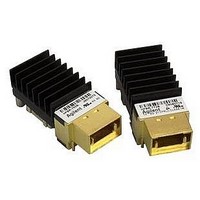
HFBR-772BWZ
Description
XMITTER FO 12X2.7GBD
Manufacturer
Avago Technologies US Inc.
Specifications of HFBR-772BWZ
Wavelength
850nm
Spectral Bandwidth
0.4nm
Capacitance
0.1µF
Connector Type
MTP® (MPO)
Data Rate Max
2.7Gbps
Data Transmission Distance
600m
Supply Current
320mA
Operating Temperature Range
0°C To +80°C
Peak Wavelength
850nm
Supply Voltage Range
3.135V To 3.465V
Lead Free Status / RoHS Status
Lead free / RoHS Compliant
Current - Dc Forward (if)
-
Voltage - Forward (vf) Typ
-
Voltage - Dc Reverse (vr) (max)
-
Lead Free Status / RoHS Status
Lead free / RoHS Compliant, Lead free / RoHS Compliant
Available stocks
Company
Part Number
Manufacturer
Quantity
Price

Part Number:
HFBR-772BWZ
Manufacturer:
AVAGO/安华高
Quantity:
20 000


Receiver Electrical Characteristics
(T
Notes:
1. I
2. Measured over the range 4 MHz to 2 GHz.
3. ∆V
4. Inter-channel Skew is defined for the condition of equal amplitude, zero ps skew input signals. Input power at –10 dBm.
5. Rise and Fall Times are measured between the 20% and 80% levels using a 500 MHz square wave signal.
6. The Signal Detect output will change from logic “0” (Low) to “1” (High) within the specified assert time for a step transition in optical
7. The Signal Detect output will change from logic “1” (High) to “0” (Low) within the specified de-assert time for a step transition in
7
Parameter
Power Dissipation
Differential Output Impedance
Data Output Differential Peak-to-Peak
Inter-channel Skew
Differential Data Output Rise/Fall Time
Control I/O
LVTTL & LVCMOS Output Voltage High
Compatible
Supply Current
Voltage Swing
Signal Detect Assert Time (OFF-to-ON)
C
between the outputs and any resistive terminations. See Figure 7 for recommended termination.
Data Output Voltage. ∆V
recommended coupling capacitors and with a 2500 MBd, 8B10B serial encoded data pattern.
input power from the de-asserted condition to the specified asserted optical power level on all 12 channels.
optical input power from the specified asserted optical power level to the de-asserted condition on any 1 channel.
= 0 °C to +80 °C, V
CC
R is the dc supply current, dependent upon the number of active channels, where the Data Outputs are ac coupled with capacitors
DOUTP-P
= ∆V
De-assert Time (ON-to-OFF)
DOUTH
Output Voltage Low
CC
– ∆V
= 3.3 V ± 5%, Typical T
DOUTH
DOUTL
and ∆V
, where ∆V
DOUTL
I
P
Symbol
Z
DV
t
t
t
V
V
CCR
r
SDA
SDD
DISR
OUT
/t
OL
OH
DOUTH
DOUTP-P
f
= V
DOUT+
C
= High State Differential Data Output Voltage and ∆V
= +40 °C, V
Min.
80
2.5
450
V
– V
EE
DOUT–
, measured with a 100 Ω differential load connected with the
CC
= 3.3 V)
400
1.3
100
600
100
110
170
190
3.1
Typ.
Max.
445
1.55
120
750
150
150
0.4
V
CC
Unit
mA
W
W
mV
ps
ps
µs
µs
V
V
P-P
DOUTL
= Low State Differential
Reference
(Conditions)
1, Fig. 5
(I
(I
2, Fig. 8, 10
3, Figs. 7, 8
4
5
6
7
OL
OH
= 4.0 mA)
= -0.5 mA)
Related parts for HFBR-772BWZ
Image
Part Number
Description
Manufacturer
Datasheet
Request
R

Part Number:
Description:
RECEIVER FIBER OPTIC 600NM 5MBD
Manufacturer:
Avago Technologies US Inc.
Datasheet:

Part Number:
Description:
RECEIVER FIBER OPTIC 600NM 40KBD
Manufacturer:
Avago Technologies US Inc.
Datasheet:

Part Number:
Description:
RCVR FIBER OPTIC INTERBUS-S
Manufacturer:
Avago Technologies US Inc.
Datasheet:

Part Number:
Description:
RCVR OPT HI PERF VERS LINK HORZ
Manufacturer:
Avago Technologies US Inc.
Datasheet:
Part Number:
Description:
RCVR OPT HI PERF VERS LINK HORZ
Manufacturer:
Avago Technologies US Inc.
Datasheet:

Part Number:
Description:
XMITTER FIBER OPTIC 600NM 5MBD
Manufacturer:
Avago Technologies US Inc.
Datasheet:

Part Number:
Description:
XMITTER FIBER OPTIC 600NM 40KBD
Manufacturer:
Avago Technologies US Inc.
Datasheet:

Part Number:
Description:
XMITTER FIBER OPTIC HIGH PWR ST
Manufacturer:
Avago Technologies US Inc.
Datasheet:
Part Number:
Description:
XMITTER VERSATILE LINK HORZ
Manufacturer:
Avago Technologies US Inc.
Datasheet:
Part Number:
Description:
XMITTER VERSATILE LINK HORZ
Manufacturer:
Avago Technologies US Inc.
Datasheet:

Part Number:
Description:
XMITTER OPT HI PERFORMANCE VERT
Manufacturer:
Avago Technologies US Inc.
Datasheet:

Part Number:
Description:
Fiber Optic Transmitters, Receivers, Transceivers Versatile Link Horiz
Manufacturer:
Avago Technologies US Inc.
Datasheet:
Part Number:
Description:
Fiber Optic Transmitters, Receivers, Transceivers Versatile Link Horiz
Manufacturer:
Avago Technologies US Inc.
Datasheet:
Part Number:
Description:
Fiber Optic Transmitters, Receivers, Transceivers Versatile Link Horiz
Manufacturer:
Avago Technologies US Inc.
Datasheet:

Part Number:
Description:
FIBER OPTIC TRANSMITTER 660NM
Manufacturer:
Avago Technologies US Inc.
Datasheet: