HW-USB-II-G Xilinx Inc, HW-USB-II-G Datasheet - Page 18
HW-USB-II-G
Manufacturer Part Number
HW-USB-II-G
Description
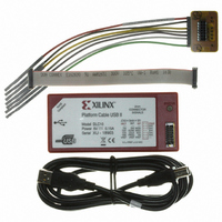
PLATFORM CABLE USB II
Manufacturer
Xilinx Inc
Datasheet
1.HW-USB-II-G.pdf
(35 pages)
Specifications of HW-USB-II-G
Accessory Type
USB Platform Cable
For Use With/related Products
Xilinx FPGA, CPLDS, Platform Flash PROMs, XC18V00 PROMs, System ACE MPM
Lead Free Status / RoHS Status
Lead free / RoHS Compliant
Other names
122-1572
Available stocks
Company
Part Number
Manufacturer
Quantity
Price
Company:

Part Number:
HW-USB-II-G
Manufacturer:
APEC
Quantity:
4 000


X-Ref Target - Figure 18
Notes:
1.
2.
3.
4.
5.
Indirect SPI
When used with Xilinx design tools, Platform Cable USB II can be used to indirectly program some third-party SPI serial
flash PROMs via the target FPGA's JTAG port. For a complete description on using Platform Cable USB II for indirect
programming of third-party SPI serial flash PROMs and for a complete list of supported SPI serial flash memories, refer to
XAPP974, Indirect Programming of SPI Serial Flash PROMs with Spartan-3A FPGAs.
Indirect BPI
When used with Xilinx design tools, Platform Cable USB II can be used to indirectly program Platform Flash XL, or some
third-party NOR flash memories (BPI PROMs) via the target FPGA's JTAG port. For a description of the indirect Platform
Flash programming solution, see UG438, Platform Flash XL User Guide.
DS593 (v1.2.1) March 17, 2011
The pin names for a ST Microsystems M25Pxx serial flash device are shown in this example. SPI flash devices from other vendors can have
different pin names and requirements. Refer to the SPI flash data sheet for the equivalent pins and device requirements.
The example shows the interconnect and device requirements for a Xilinx Spartan-3E FPGA. Other SPI-capable FPGAs can have different
pin names and requirements. Please refer to the FPGA data sheet for equivalent pins and device requirements.
The cable uses an open-drain driver to control the pseudo ground (PGND) signal — an external pull-up resistor is required.
Attach the following 2-mm connector pins to digital ground: 3, 5, 7, 9 and 11.
Typically, an FPGA and other slave SPI devices (not shown) are connected to the SPI bus. The other devices on the SPI bus must be disabled
when the cable is connected to the 2-mm connector to avoid signal contention. When a Xilinx FPGA is connected to the SPI bus, the cable
holds the FPGA PROG_B pin Low to insure the FPGA SPI pins are 3-stated.
+2.5V
Spartan-3E
+3.3V
FPGA
GND
(2)
+1.2V
PROG_B
CSO_B
CCLK
MOSI
DIN
Figure 18: Example of Direct SPI Topology
SPI Bus
+ 2.5V
www.xilinx.com
(5)
+ 3.3V
D
Q
S
C
Connector
2 mm
10
13
2
8
4
6
*
V
MISO
MOSI
SS
SCK
PGND
GND
REF
M25Pxx
SPI Flash
ST Micro
(4)
+3.3V
VCC
GND
(1)
Platform Cable USB II
HOLD
W
DS593_18_021508
‘1’
‘1’
18
Related parts for HW-USB-II-G
Image
Part Number
Description
Manufacturer
Datasheet
Request
R

Part Number:
Description:
PLATFORM CABLE USB
Manufacturer:
Xilinx Inc
Datasheet:

Part Number:
Description:
IC CABLE
Manufacturer:
Xilinx Inc
Datasheet:

Part Number:
Description:
BOARD ADAPTER AND FLY LEADS
Manufacturer:
Xilinx Inc
Datasheet:

Part Number:
Description:
XLXHW-LICENSE-DONGLE-USB-G USB DONGLE OP
Manufacturer:
Xilinx Inc

Part Number:
Description:
IC CPLD .8K 36MCELL 44-VQFP
Manufacturer:
Xilinx Inc
Datasheet:

Part Number:
Description:
IC CPLD 72MCRCELL 10NS 44VQFP
Manufacturer:
Xilinx Inc
Datasheet:

Part Number:
Description:
IC CPLD 1.6K 72MCELL 64-VQFP
Manufacturer:
Xilinx Inc
Datasheet:

Part Number:
Description:
IC CR-II CPLD 64MCELL 44-VQFP
Manufacturer:
Xilinx Inc
Datasheet:

Part Number:
Description:
IC CPLD 1.6K 72MCELL 100-TQFP
Manufacturer:
Xilinx Inc
Datasheet:

Part Number:
Description:
IC CR-II CPLD 64MCELL 56-BGA
Manufacturer:
Xilinx Inc
Datasheet:

Part Number:
Description:
IC CPLD 72MCRCELL 7.5NS 44VQFP
Manufacturer:
Xilinx Inc
Datasheet:
Part Number:
Description:
IC CR-II CPLD 64MCELL 100-VQFP
Manufacturer:
Xilinx Inc
Datasheet:
Part Number:
Description:
IC CPLD 1.6K 72MCELL 100-TQFP
Manufacturer:
Xilinx Inc
Datasheet:

Part Number:
Description:
IC CPLD 72MCRCELL 7.5NS 64VQFP
Manufacturer:
Xilinx Inc
Datasheet:
Part Number:
Description:
IC CPLD 1.6K 72MCELL 100-TQFP
Manufacturer:
Xilinx Inc
Datasheet: