PMF30XA1 Microchip Technology, PMF30XA1 Datasheet - Page 4
PMF30XA1
Manufacturer Part Number
PMF30XA1
Description
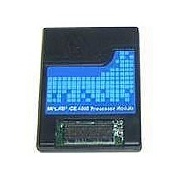
PROCESSOR MODULE FOR ICE4000
Manufacturer
Microchip Technology
Datasheet
1.PMF18WD0.pdf
(10 pages)
Specifications of PMF30XA1
Accessory Type
Processor Module
Product
Microcontroller Modules
Core Processor
dsPIC30F
Lead Free Status / RoHS Status
Lead free / RoHS Compliant
For Use With/related Products
ICE4000
For Use With
ICE4000 - EMULATOR MPLAB-ICE 4000 POD
Lead Free Status / RoHS Status
Lead free / RoHS Compliant, Lead free / RoHS Compliant
Other names
PMF30XA1R
PMF30XA1R
PMF30XA1R


MPLAB
4.3.2
If the target application is selected to provide the clock
source, the target board must also be selected to
power the emulator processor (see the MPLAB ICE
4000 on-line help file in MPLAB IDE (Help>Topics) or
the MPLAB
“Using a Target Board Clock”).
At low voltage, the maximum speed of the processor
will be limited to the rated speed of the device under
emulation.
An oscillator circuit on the device adapter generates a
clock to the processor module and buffers the clock
circuit on the target board. In this way, the MPLAB ICE
4000 emulator closely matches the oscillator options of
the actual device. All oscillator modes are supported
(as documented in the device’s data sheet) except as
noted in Section 3.0 “Emulator-Related Issues”. The
OSC1 and OSC2 inputs of the device adapter have a
5 pF to 10 pF load. Be aware of this when using a
crystal in HS, XT, LP or LF modes, or an RC network in
RC mode.
The frequency of the emulated RC network may vary
relative to the actual device due to emulator circuitry. If
a specific frequency is important, adjust the RC values
to achieve the desired frequency. Another alternative
would be to allow the emulator to provide the clock as
described in Section 4.3.1 “Clock Source from
Emulator”.
When using the target board clock, the system’s
operating voltage is between 2.5V and 5.5V.
4.4
All CMOS chips are susceptible to electrostatic
discharge (ESD). In the case of the processor modules,
the pins of the CMOS emulator are directly connected
to the target connector, making the chip vulnerable to
ESD. ESD can also induce latch-up in CMOS chips,
causing excessive current through the chip and
possible damage. MPLAB ICE 4000 has been
designed to minimize potential damage by implement-
ing overcurrent protection. However, care should be
given to minimizing ESD conditions while using the
system.
During development, contention on an I/O pin is
possible (e.g., when an emulator pin is driving a ‘1’ and
the target board is driving a ‘0’). Prolonged contention
may cause latch-up and damage to the emulator chip.
One possible precaution is to use current limiting
resistors (~100 Ω) during the development phase on
bidirectional I/O pins. Using limiting resistors can also
help avoid damage to modules, device adapters and
pods that occurs when a voltage source is accidentally
connected to an I/O pin on the target board.
DS51298E-page 4
CLOCK SOURCE FROM THE TARGET
APPLICATION
ESD Protection and Electrical
Overstress
®
ICE 4000 User’s Guide (DS51490),
®
ICE 4000
Preliminary
4.5
The MPLAB ICE 4000 system allows the option of
“freezing” peripheral operation or allowing them to
continue operating when the processor is halted. This
option is configured in the MPLAB IDE.
This function is useful to halt an on-board timer while at
a break point. At a break point, and while single
stepping, interrupts are disabled.
5.0
The MPLAB ICE 4000 device adapters use a serial
EEPROM that is interrogated by MPLAB IDE to
determine what device adapter type and revision is
connected. Using this information, along with the
selected device, MPLAB IDE will determine the device
adapter configuration (i.e., there are no switches or
jumpers to be configured on the device adapters).
Two test points are provided for the use: GND (black)
and VCCME (red).
When target is selected, the “target power” LED will
illuminate on certain adapters to visually indicate Target
Power mode.
Device adapters are specified as DAFXX-N, where XX
denotes the device family (e.g., 18, 30) and N denotes
a number. See the file “Readme for MPLAB ICE
4000.txt” in the MPLAB IDE installation directory for a
list of current device adapters and the devices they
support.
Please see the MPLAB
Socket Specification (DS51194) for transition sockets
that are used with these device adapters.
Freeze Mode
DEVICE ADAPTERS
© 2005 Microchip Technology Inc.
®
ICE 2000/4000 Transition
Related parts for PMF30XA1
Image
Part Number
Description
Manufacturer
Datasheet
Request
R

Part Number:
Description:
Manufacturer:
Microchip Technology Inc.
Datasheet:
Part Number:
Description:
Manufacturer:
Microchip Technology Inc.
Datasheet:
Part Number:
Description:
Manufacturer:
Microchip Technology Inc.
Datasheet:
Part Number:
Description:
Manufacturer:
Microchip Technology Inc.
Datasheet:
Part Number:
Description:
Manufacturer:
Microchip Technology Inc.
Datasheet:
Part Number:
Description:
Manufacturer:
Microchip Technology Inc.
Datasheet:
Part Number:
Description:
Manufacturer:
Microchip Technology Inc.
Datasheet:
Part Number:
Description:
Manufacturer:
Microchip Technology Inc.
Datasheet: