AC164132 Microchip Technology, AC164132 Datasheet
AC164132
Specifications of AC164132
Available stocks


Related parts for AC164132

AC164132 Summary of contents
Page 1
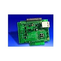
... Fast 100 Mbps Ethernet PICtail™ Plus Daughter Board Overview The Fast 100 Mbps Ethernet PICtail™ Plus Daughter Board (AC164132 Ethernet demonstration board for evaluating Microchip Technology’s ENC424J600 and ENC624J600 stand-alone 10/100 Ethernet controllers expansion board compatible with many PICtail and PICtail Plus host boards, including the Explorer 16, PIC32 I/O Expansion Board, PICDEM.net™ ...
Page 2
PIC18 Explorer The PIC18 Explorer uses the PICtail Daughter Board thru-hole headers to interface using SPI mode, much like the PICDEM.net 2 connection. Insert the Fast 100 Mbps Ethernet PICtail Plus Daughter Board J3 and J4 right angle headers into ...
Page 3
JP3 JP3, when shorted, will connect the ENC624J600 CLKOUT signal, after level shifting, to the PICtail connector (J4 Pin 5). If using the PIC18 Explorer, this function may be used to clock the PIC MCU via the OSC1 input. However, ...
Page 4
Signal Interface The pinout of the Fast 100 Mbps Ethernet PICtail Plus depends upon the jumper settings and which physical connector is used. PICtail Daughter Board Dual Row Right Angle Header (J3, J4, J5) The J3 and J4 headers are ...
Page 5
SPI1 If the PICtail Daughter Board is mated to the topmost SPI1 slot on the Explorer 16 or PIC32 I/O Expansion Board, the following connections will be made: SPI1 Mating Connections J2 Mating PICtail™ Pin Pin Daughter Board 3 3 ...
Page 6
PICtail Plus (Parallel, J1) The J1 board edge contacts are available for evaluating the ENC624J600 device’s Parallel Interface modes. Due to the large number of pins required to support a parallel interface, only the Explorer 16 and PIC32 I/O Expansion ...
Page 7
All PSP Modes The J1 parallel interface connector has several fixed power and control signals that apply to all PSP modes and do not change, regardless of the jumper settings. These common signals are shown below: Common Signal Connections for ...
Page 8
PSP Modes 1 and 2 For PSP Mode 1 (PSPCFG1/4 = PSPCFG2 = PSPCFG3 = GND) and PSP Mode 2 (PSPCFG1 PSPCFG2 = PSPCFG3 = GND) with direct addressing (PMA shorted), the ENC624J600 PSP ...
Page 9
When jumpered for indirect addressing (PMA open), the ENC624J600 PSP connections simplify to the following: Interface Signal Connections for PSP Modes 1 and 2 (Indirect Addressing) Signal Name J1 Pin ENC624J600 ...
Page 10
PSP Modes 3 and 4 For PSP Mode 3 (PSPCFG2 = V (PSPCFG1/4 = PSPCFG2 = V shorted), the ENC624J600 PSP interface signals are connected as follows: Interface Signal Connections for PSP Modes 3 and 4 (Direct Addressing) Signal Name ...
Page 11
The PICtail Daughter Board has the WRL/B0SEL signal connected to WRH/B1SEL, so only 16-bit word writes are possible. Writes to the high or low byte, individually, cannot be performed. When jumpered for indirect addressing (PMA open), the ...
Page 12
PSP Modes 5 and 6 For PSP Mode 5 (PSPCFG1/4 = PSPCFG2 = GND, PSPCFG3 = V (PSPCFG1/4 = PSPCFG3 = V shorted), the ENC624J600 PSP interface signals are connected as follows: Interface Signal Connections for PSP Modes 5 and ...
Page 13
When jumpered for indirect addressing (PMA open), the ENC624J600 PSP connections simplify to the following: Interface Signal Connections for PSP Modes 5 and 6 (Indirect Addressing) Signal Name J1 Pin ENC624J600 84 AL (1) ( ...
Page 14
PSP Modes 9 and 10 For PSP Mode 9 (PSPCFG1/4 = GND, PSPCFG2 = PSPCFG3 = V (PSPCFG1&4 = PSPCFG2 = PSPCFG3 = V connected as follows: Interface Signal Connections for PSP Modes 9 and 10 Signal Name J1 Pin ...
Page 15
Board Design Theory Automatic Parallel Interface Pinout Changes U1, U2, U3, U5, U13 and U14 are bus switches and glue logic for the purpose of changing the pinout of the parallel PICtail Plus board edge contacts. They are unnecessary and ...
Page 16
The Microchip TCP/IP Stack software automatically controls the MDIX state (if present) by randomly toggling the MDIX pin when no Ethernet link is detected. Random timing is used to ensure that two identical devices powered identical time ...
Page 17
PICtail Daughter Board Power Interface U6, D1 and R4 create a power switching circuit to allow both the PICDEM.net 2 and PIC18 Explorer motherboards to be automatically supported without using jumpers to select between the two. The +5V net powers ...
Page 18
NOTES: 18 ...
Page 19
NOTES: 19 ...
Page 20
... Microchip Technology Inc. • 2355 West Chandler Blvd. • Chandler, AZ 85224-6199 The Microchip name and logo and the Microchip logo are registered trademarks of Microchip Technology Incorporated in the U.S.A. and other countries. PICtail and PICDEM.net are trademarks of Microchip Technology Incorporated in the U.S.A. and other countries. All other trademarks mentioned herein are property of their respective companies. © ...