AC164132 Microchip Technology, AC164132 Datasheet - Page 2
AC164132
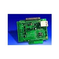
Manufacturer Part Number
AC164132
Description
BOARD DAUGHTER PICTAIL ETHERNET
Manufacturer
Microchip Technology
Series
PICtail™ Plusr
Type
Controllers & Processorsr
Datasheet
1.AC164132.pdf
(20 pages)
Specifications of AC164132
Main Purpose
Interface, Ethernet Control
Embedded
No
Utilized Ic / Part
ENC424J600, ENC624J600
Primary Attributes
Fast 100 Mbps Ethernet
Secondary Attributes
Requires Pictail™ or Pictail™ Plus Host Board
Ethernet Connection Type
10/100 Base-T, IEEE 802.3
Data Rate
100 Mbps
Memory Type
EEPROM
Interface Type
Ethernet, SPI
Operating Voltage
3.3 V to 5 V
Operating Temperature Range
- 40 C to + 85 C
Data Bus Width
8 bit
Product
Modules
Silicon Manufacturer
Microchip
Silicon Core Number
AC164132
Kit Application Type
Communication & Networking
Application Sub Type
Ethernet
Silicon Family Name
PICtail
For Use With/related Products
DM240001, DM183032
Lead Free Status / RoHS Status
Lead free / RoHS Compliant
Lead Free Status / RoHS Status
Lead free / RoHS Compliant, Lead free / RoHS Compliant
Available stocks
Company
Part Number
Manufacturer
Quantity
Price
Company:

Part Number:
AC164132
Manufacturer:
Microchip Technology
Quantity:
135


After appropriately connecting the PICtail Daughter Board to the host motherboard, apply
power to the host motherboard. If an Ethernet cable is attached and a link partner is also
attached at the far end of the cable, the green Ethernet link status LED will automatically
turn on. The orange or amber RX/TX activity LED will also blink if Ethernet traffic is sent to
the PICtail Daughter Board. If the link LED does not light as expected, it is possible that the
TX and RX Ethernet data pairs are swapped. To test this, a crossover Ethernet cable could
be used, or appropriate firmware may be written, to toggle the MDIX control signal which will
swap the TX and RX data pairs on the PICtail Daughter Board.
Further evaluation will require the use of a TCP/IP Stack software library running on the host
motherboard to appropriately control the Ethernet interface. Microchip TCP/IP Stack,
Version 5.00 and later, can be used with this PICtail Daughter Board. The latest Microchip
TCP/IP Stack version should be downloaded from the Microchip web site at
www.microchip.com/tcpip. After obtaining and installing the stack, further getting started
information is available in the TCP/IP Stack Help. Instead of building the stack, it is strongly
recommended that first time testing be done using one of the stack’s precompiled .hex
files, if available, for the hardware and interface mode in use.
Schematic and Bill of Materials
The Fast 100 Mbps Ethernet PICtail Plus schematic and bill of materials are not provided
here. They may be obtained from the Microchip web site at www.microchip.com/ethernet or
by installing the latest Microchip TCP/IP Stack available from www.microchip.com/tcpip.
Jumper Configuration
The Fast 100 Mbps Ethernet PICtail Plus board has seven jumpers that control the opera-
tional mode of the ENC624J600 and enable various features. The jumper functions are
summarized in the following table:
Jumper Functions
JP2
JP2 lies directly in series with the +3.3V power supply for the ENC624J600 and Ethernet
magnetics (3V3ETH). To power the ENC624J600 from an external source, remove the JP2
shunt and connect an external power supply to the red 3V3ETH Test Point (TP2). To
measure the ENC624J600 and magnetics current usage, replace the JP2 shunt with a cur-
rent meter. Because the Ethernet solution will draw in excess of 200 mA when all features
are enabled, apply caution before attempting to measure the current using a 200 mA fused
current measurement scale, available on many handheld multimeters.
For normal device operation, JP2 must be shorted by a jumper shunt.
2
PIC18 Explorer
The PIC18 Explorer uses the PICtail Daughter Board thru-hole headers to interface using
SPI mode, much like the PICDEM.net 2 connection. Insert the Fast 100 Mbps Ethernet
PICtail Plus Daughter Board J3 and J4 right angle headers into the J9 and J3 female
headers on the PIC18 Explorer, respectively. Pin 1 on J3 of the PICtail Daughter Board,
labeled “ADJ”, must align with Pin 1 on J9 of the PIC18 Explorer (also labeled “ADJ”).
Jumper
JP10
JP11
JP2
JP3
JP7
JP8
JP9
Bridge
Bridge
Bridge
Bridge
2-Way
2-Way
2-Way
Type
ENC624J600 Power Control and Current Sense
ENC624J600 CLKOUT Enable to PICtail Interface
PIC
Connection Enable
PIC MCU PMP PMA<x:8> to ENC624J600 A<x:8>
Connection Enable
ENC624J600 PSPCFG2 and Pinout Control
ENC624J600 PSPCFG3 and Pinout Control
ENC624J600 PSPCFG1/PSPCFG4 and Pinout Control
®
MCU PMP PMA<x:8> to ENC624J600 AD<x:8>
Description
Related parts for AC164132
Image
Part Number
Description
Manufacturer
Datasheet
Request
R

Part Number:
Description:
Manufacturer:
Microchip Technology Inc.
Datasheet:
Part Number:
Description:
Manufacturer:
Microchip Technology Inc.
Datasheet:
Part Number:
Description:
Manufacturer:
Microchip Technology Inc.
Datasheet:
Part Number:
Description:
Manufacturer:
Microchip Technology Inc.
Datasheet:
Part Number:
Description:
Manufacturer:
Microchip Technology Inc.
Datasheet:
Part Number:
Description:
Manufacturer:
Microchip Technology Inc.
Datasheet:
Part Number:
Description:
Manufacturer:
Microchip Technology Inc.
Datasheet:
Part Number:
Description:
Manufacturer:
Microchip Technology Inc.
Datasheet: