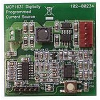
MCP1631RD-MCC1 Microchip Technology, MCP1631RD-MCC1 Datasheet - Page 9

MCP1631RD-MCC1
Manufacturer Part Number
MCP1631RD-MCC1
Description
REFERENCE DESIGN FOR MCP1631HV
Manufacturer
Microchip Technology
Type
Battery Managementr
Datasheets
1.MCP1631VHVT-330EST.pdf
(34 pages)
2.MCP1631HV-330EST.pdf
(54 pages)
3.MCP1631RD-MCC2.pdf
(20 pages)
4.MCP1631RD-MCC2.pdf
(328 pages)
5.MCP1631RD-MCC1.pdf
(28 pages)
Specifications of MCP1631RD-MCC1
Main Purpose
Power Management, Battery Charger
Embedded
Yes, MCU, 8-Bit
Utilized Ic / Part
MCP1631HV, PIC16F883
Primary Attributes
1 ~ 2 Cell- Li-Ion, 1 ~ 4 Cell- NiCd/NiMH
Secondary Attributes
Status LEDs
Supported Devices
MCP1631HV, PIC16F883 Device Type
Tool / Board Applications
Power Management-Battery Management
Development Tool Type
Reference Design
Input Voltage
5.5 V to 16 V
Product
Power Management Modules
Mcu Supported Families
MCP1631HV/PIC16F883 Family
Silicon Manufacturer
Microchip
Silicon Core Number
MCP1631HV
Kit Application Type
Reference Design
Application Sub Type
Battery Charger
Kit Contents
Board Only
Lead Free Status / RoHS Status
Lead free / RoHS Compliant
For Use With/related Products
MCP1631HV, PIC16F883
Lead Free Status / RoHS Status
Lead free / RoHS Compliant
2.0
Note:
for typical values = +25°C.
FIGURE 2-1:
Temperature.
FIGURE 2-2:
Hysteresis vs. Temperature.
FIGURE 2-3:
Temperature.
© 2008 Microchip Technology Inc.
Note:
0.068
0.067
0.066
0.065
0.064
0.063
0.062
0.061
2.89
2.88
2.87
2.86
2.85
2.84
2.83
2.82
2.81
4.00
3.80
3.60
3.40
3.20
3.00
2.80
Unless otherwise noted, V
2.8
TYPICAL PERFORMANCE CURVES
The graphs and tables provided following this note are a statistical summary based on a limited number of
samples and are provided for informational purposes only. The performance characteristics listed herein are
not tested or guaranteed. In some graphs or tables, the data presented may be outside the specified
operating range (e.g., outside specified power supply range) and therefore outside the warranted range.
V
DD
Device Turn Off
Device Turn On
= +5.0V
Ambient Temperature (°C)
Ambient Temperature (°C)
Ambient Temperature (°C)
Undervoltage Lockout vs.
Undervoltage Lockout
Input Quiescent Current vs.
V
DD
V
DD
= +3.3V
= +3.0V
IN
= 3.0V to 5.5V, F
V
DD
= +4.0V
V
DD
= +5.5V
OSC
MCP1631/HV/MCP1631V/VHV
= 1 MHz with 10% Duty Cycle, C
FIGURE 2-4:
Temperature (MCP1631/MCP1631V).
FIGURE 2-5:
vs. Temperature.
FIGURE 2-6:
Threshold vs. Temperature.
4.00
3.70
3.40
3.10
2.80
2.50
2.20
1.90
1.60
1.30
1.00
1.60
1.50
1.40
1.30
1.20
1.10
1.00
1.70
1.60
1.50
1.40
1.30
1.20
1.10
1.00
0.90
0.80
V
V
DD
DD
IN
= +3.3V
= +3.0V
V
V
DD
= 0.1 µF, V
DD
Ambient Temperature (°C)
Ambient Temperature (°C)
= +3.0V
= +3.3V
Ambient Temperature (°C)
V
DD
Shutdown Current vs.
Oscillator Input Threshold
Oscillator Disable Input
V
= +3.3V
DD
V
= +4.0V
DD
IN
= +4.0V
for typical values = 5.0V, T
V
V
DD
DD
V
= +5.0V
= +4.0V
V
DD
DD
V
= +5.0V
DD
= +3.0V
DS22063B-page 9
= +5.0V
V
V
V
DD
DD
DD
= +5.5V
= +5.5V
= +5.5V
A


