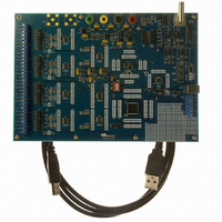
CDB5376 Cirrus Logic Inc, CDB5376 Datasheet - Page 9

CDB5376
Manufacturer Part Number
CDB5376
Description
EVALUATION BOARD FOR CS5376
Manufacturer
Cirrus Logic Inc
Datasheets
1.CS5371A-ISZR.pdf
(32 pages)
2.CS4373A-ISZ.pdf
(34 pages)
3.CS5376A-IQZR.pdf
(106 pages)
4.CDB5378.pdf
(16 pages)
5.CDB5376.pdf
(80 pages)
6.CDB5376.pdf
(16 pages)
Specifications of CDB5376
Main Purpose
Seismic Evaluation System
Embedded
Yes, MCU, 8-Bit
Utilized Ic / Part
CS3301A, CS3302A, CS4373A, CS5372A, CS5376A
Primary Attributes
Quad Digital Filter
Secondary Attributes
Graphical User Interface, SPI™ & USB Interfaces
Processor To Be Evaluated
CS330x, CS4373A, CS537x
Interface Type
USB
Lead Free Status / RoHS Status
Contains lead / RoHS non-compliant
Lead Free Status / RoHS Status
Lead free / RoHS Compliant, Contains lead / RoHS non-compliant
Other names
598-1778
2.
The CS3301A is a low-noise chopper-stabilized
CMOS differential input, differential output ampli-
fier for precision analog signals between DC and
2 kHz. It has multiplexed inputs, rough / fine out-
puts and programmable gains of x1, x2, x4, x8,
x16, x32, and x64.
The amplifier’s performance makes it ideal for
low-frequency, high dynamic range applications
requiring low distortion and minimal power con-
sumption. It’s optimized for use in acquisition sys-
tems
single/dual ∆Σ modulators and the CS5376A quad
digital filter or the CS5373A ∆Σ modulator and
CS5378 digital filter.
Figure 3 on page 9
a 4-channel acquisition system using four
CS3301A, two CS5372A, one CS4373A, and one
CS5376A.
DS757F1
GENERAL DESCRIPTION
Hydrophone
Hydrophone
Hydrophone
Hydrophone
Geophone
Geophone
Geophone
Geophone
designed
Sensor
Sensor
Sensor
Sensor
or
or
or
or
Figure 4 on page 10
shows the system architecture of
around
the
Figure 3. Multi-Channel System Architecture
shows the system
M
U
X
M
U
X
M
U
X
M
U
X
CS5371A/72A
AMP
AMP
AMP
AMP
CS3301A
CS3302A
CS3301A
CS3302A
CS3301A
CS3302A
CS3301A
CS3302A
Switch
Switch
MUX
MUX
Modulator
Modulator
CS5371A
CS5372A
CS5371A
CS5372A
architecture of a single channel acquisition system
using a CS3301A, CS5373A, and CS5378.
2.1
2.1.1
The amplifier analog inputs are designed for differ-
ential sensors. Input multiplexing simplifies sys-
tem connections by providing separate inputs for a
sensor and test DAC (INA, INB) as well as an in-
ternal termination for noise tests. The MUX0,
MUX1 digital pins determine which multiplexed
input is connected to the amplifier.
2.1.2
The amplifier analog outputs are separated into
rough charge / fine charge signals to easily connect
to the CS5371A/72A/73A modulator inputs. Each
differential output requires two series resistors and
a differential capacitor to create the modulator anti-
alias RC filter.
∆Σ
∆Σ
Analog Signals
Analog Inputs
Analog Outputs
CS5376A
Digital Filter
CS4373A
Test
DAC
System Telemetry
Communication
Configuration
µController
EEPROM
Interface
CS3301A
or
9


