MCP3421EV Microchip Technology, MCP3421EV Datasheet
MCP3421EV
Specifications of MCP3421EV
Available stocks


Related parts for MCP3421EV

MCP3421EV Summary of contents
Page 1
... SS SDA SCL 3 4 © 2009 Microchip Technology Inc. Description The MCP3421 is a single channel low-noise, high accuracy ΔΣ A/D converter with differential inputs and bits of resolution in a small SOT-23-6 package. The on-board precision 2.048V reference voltage enables an input range of ±2.048V differentially (Δ ...
Page 2
... MCP3421 NOTES: DS22003E-page 2 © 2009 Microchip Technology Inc. ...
Page 3
... This parameter is ensured by characterization and not 100% tested. 8: This parameter is ensured by design and not 100% tested. © 2009 Microchip Technology Inc. †Notice: Stresses above those listed under “Maximum Rat- ings” may cause permanent damage to the device. This is a stress rating only and functional operation of the device at those or any other conditions above those indicated in the operational listings of this specification is not implied ...
Page 4
... Tested at PGA = 5.0V and DR = 3.75 SPS DD nV/° 5. and PGA = and PGA = +25°C A ppm +25° 2.7V to 5.5V PGA = +25° 2.7V to 5.5V PGA = 1 V µ 5.0V DD µ 3.0V DD µ mA +5. 100 kHz SCL µA µ 5.5V IH µ GND © 2009 Microchip Technology Inc. ...
Page 5
... TEMPERATURE SPECIFICATIONS Electrical Characteristics: Unless otherwise indicated, T Parameters Temperature Ranges Specified Temperature Range Operating Temperature Range Storage Temperature Range Thermal Package Resistances Thermal Resistance, 6L SOT-23 © 2009 Microchip Technology Inc. = -40°C to +85° Sym Min Typ Max T -40 — + -40 — +125 ...
Page 6
... MCP3421 NOTES: DS22003E-page 6 © 2009 Microchip Technology Inc. ...
Page 7
... PGA = 4 PGA = 8 10 PGA = PGA = 1 -10 -15 -20 -60 -40 - 100 120 140 Temperature (°C) FIGURE 2-3: Offset Error vs. Temperature. © 2009 Microchip Technology Inc. = +5. +25° 7.5 5.0 2.5 0.0 -100 -75 5 5.5 FIGURE 2-4: Voltage. 3.0 2.0 1.0 0.0 -1 ...
Page 8
... V = 2.7V -100 DD -110 -120 0.1 0.1 FIGURE 2-11 / REF = 2. 100 120 140 Temperature (°C) OSC Drift vs. Temperature. Data Rate = 3.75 SPS 1 10 100 1k 10k 1 10 100 1000 10000 Input Signal Frequency (Hz) Frequency Response. © 2009 Microchip Technology Inc. ...
Page 9
... C is the package pin capacitance and PIN typically about 4 pF. D and D are the ESD diodes the differential input sampling capacitor. SAMPLE © 2009 Microchip Technology Inc. Table 3-1. Description 2 C Interface 2 C Interface -) 3.2 Supply Voltage ( the power supply pin for the device ...
Page 10
... MHz). The High-Speed mode is not recommended for 0. LEAKAGE 0. ±1 nA Leakage Current at Analog Pin LEAKAGE SS = Sampling Switch R = Sampling Switch Resistor Sample Capacitance SAMPLE ESD Protection Diode 1 2 less than 2.7V. DD Sampling Switch SAMPLE (3.2 pF) © 2009 Microchip Technology Inc. ...
Page 11
... If the supply voltage falls below this threshold, the device will be held in a reset condition. The typical hysteresis value is approximately 200 mV. © 2009 Microchip Technology Inc. The POR circuit is shut-down during the low-power standby mode. Once a power-up event has occurred, the ...
Page 12
... Self-Calibration The device performs a self-calibration of offset and gain for each conversion. This provides reliable conversion results from conversion-to-conversion over variations in temperature as well as power supply fluctuations. Ω Z (f) = 2.25 M /PGA IN 2-11) may not give enough © 2009 Microchip Technology Inc. ...
Page 13
... Where User programmable bit resolution: 12,14,16 © 2009 Microchip Technology Inc. Table 4-1 shows the LSB size of each conversion rate setting. The measured unknown input voltage is obtained by multiplying the output codes with LSB. See the following section for the input voltage calculation using the output codes ...
Page 14
... LSB(15.625μV)/PGA = - 31.25 (μV)for PGA = -(2 +0+0+0+0+0+0+0+0+0+0+0+0+0+0+0+0+0) x LSB(15.625μV)/PGA = - 2.048 (V) for PGA = -(2 +0+0+0+0+0+0+0+0+0+0+0+0+0+0+0+0+0) x LSB(15.625μV)/PGA = - 2.048 (V) for PGA = 1 CONVERTING OUTPUT CODES TO INPUT VOLTAGE LSB • ----------- - = (Output Code) PGA LSB • ----------- - PGA See Table 4-1 1’s complement + +0 +0)x © 2009 Microchip Technology Inc. ...
Page 15
... RDY bit = 1 means the conversion result is not updated since the last reading. A new conversion is under processing and the RDY bit will be cleared when the new conversion result is ready © 2009 Microchip Technology Inc. 5.1.2 ONE-SHOT CONVERSION MODE (O/C BIT = Once the One-Shot Conversion (single conversion) ...
Page 16
... The user can rewrite the configuration byte any time during the device operation. Register 5-1 shows the configuration register bits. R/W-1 R/W-0 R/W-0 O Unimplemented bit, read as ‘0’ ‘0’ = Bit is cleared R/W-0 R/W bit Bit is unknown © 2009 Microchip Technology Inc. ...
Page 17
... The conversion result in Continuous Conversion mode was already read. The next new conversion data is not ready. The RDY bit stays high until a new conversion is completed. © 2009 Microchip Technology Inc. MCP3421 2 5 Serial Communications The device communicates 2 (microcontroller) through a serial I ...
Page 18
... If the device receives a write command with a new (Note 1) configuration setting, the device immediately begins a new conversion and updates the conversion data R/W ACK by RDY O/C MCP3421 2nd Byte: Configuration Byte 9 ACK by Stop Bit by MCP3421 Master © 2009 Microchip Technology Inc. ...
Page 19
... D13 is MSB (= sign bit repeated MSB of the data byte. 4: D11 is MSB (= sign bit repeated MSB of the data byte. © 2009 Microchip Technology Inc. The configuration byte follows the output data bytes. The device repeatedly outputs the configuration byte only if the Master sends clocks repeatedly after the data bytes ...
Page 20
... MCP3421 FIGURE 5-3: iming Diagram For Reading From The MCP3421 With 18-Bit Mode. DS22003E-page 20 © 2009 Microchip Technology Inc. ...
Page 21
... FIGURE 5-4: Timing Diagram For Reading From The MCP3421 With 12-Bit to 16-Bit Modes. © 2009 Microchip Technology Inc. MCP3421 DS22003E-page 21 ...
Page 22
... HIGH period of the clock signal. The data on the line must be changed during the LOW period of the clock signal. There is one clock pulse per bit of data. Each data transfer is initiated with a START condition and terminated with a STOP condition specification. 5-6. © 2009 Microchip Technology Inc. ...
Page 23
... START CONDITION ACKNOWLEDGE FIGURE 5-6: Data Transfer Sequence on I © 2009 Microchip Technology Inc. During reads, the Master (microcontroller) can terminate the current read operation by not providing an acknowledge bit (not Acknowledge (NAK)) on the last byte. In this case, the MCP3421 device releases the SDA line to allow the Master (microcontroller) to generate a STOP or repeated START condition ...
Page 24
... Conditions kHz ns ns (Note 1) ns From (Note 1) ns From (Note (Note 2, Note Time between START and STOP conditions. kHz ns ns (Note 1) ns From (Note 1) ns From (Note (Note 2, Note Time between START and STOP conditions parameter. AA © 2009 Microchip Technology Inc. ...
Page 25
... If this parameter is too long, Clock Low time (T 4: For Data Input: This parameter must be longer than Clock Low time (T SU:DAT For Data Output: This parameter is characterized, and tested indirectly by testing T © 2009 Microchip Technology Inc. = +2.7V to +5.0V. Min Typ Max < 2.7V DD — ...
Page 26
... MCP3421 SCL SU:STA T LOW T SDA HD:STA FIGURE 5- Bus Timing Data. DS22003E-page 26 T HIGH T SU:DAT T HD:DAT SU:STO T BUF 0.7V DD 0.3V DD © 2009 Microchip Technology Inc. ...
Page 27
... RC time constant. The pull-up resistor is typically chosen between 5 kΩ and 10 kΩ ranges for standard and fast modes. © 2009 Microchip Technology Inc. Input Signals MCP3421 ...
Page 28
... Excitation (b) Single-ended Input Signal Connection: Excitation Sensor R Stop Bit : 0 R MCP3421 2 Response FIGURE 6-4: Ended Input Connections. - input pins pin Sensor MCP3421 Input Signal Input Signal MCP3421 Ceramic Capacitor µF , Tantalum Capacitor µF Differential and Single- © 2009 Microchip Technology Inc. ...
Page 29
... Output Code LSB R FIGURE 6-5: Battery Voltage Measurement. © 2009 Microchip Technology Inc. 6.2.2 CURRENT MEASUREMENT Figure 6-6 shows a circuit example of current measurement. For the current measurement, the device measures the voltage across the current sensor, and converts it to current by dividing the measured voltage by a known resistance value of the current sensor ...
Page 30
... MCP6V01 MCP3421 Simple Signal Conditioning 1/2 MCP6V02 200Ω µF 20 kΩ 200Ω 3 kΩ MCP3421 1 µF 200Ω 3 kΩ 20 kΩ 1 µF 200Ω 1/2 MCP6V02 High Performance Signal © 2009 Microchip Technology Inc. ...
Page 31
... V/°C μ 320 V/°C No. of LSB/°C = ------------------------ - = 20.48 Codes/°C μ 15.625 V Where: 1 LSB = 15.625 µV with 18-bit configuration © 2009 Microchip Technology Inc. Hot Junction ( Heat ). The CJ Thermocouple Sensor ~ 40 µV° can measure 40 µV/°C FIGURE 6-10: resolution. Measurement. ...
Page 32
... MCP3421 NOTES: DS22003E-page 32 © 2009 Microchip Technology Inc. ...
Page 33
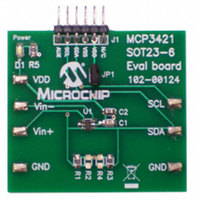
... MCP3421 Evaluation Boards The MCP3421 Evaluation Board is available from Microchip Technology Inc. This board works with Micro- chip’s PICkit™ Serial Analyzer. The user can simply connect any sensing voltage to the input test pads of the board and read conversion codes using the easy- to-use PICkit™ ...
Page 34
... MCP3421 FIGURE 7-3: Example of PICkit™ Serial User Interface. DS22003E-page 34 © 2009 Microchip Technology Inc. ...
Page 35
... Note: In the event the full Microchip part number cannot be marked on one line, it will be carried over to the next line, thus limiting the number of available characters for customer-specific information. © 2009 Microchip Technology Inc. MCP3421 Example Address Code ...
Page 36
... MCP3421 /HDG 3ODVWLF 6PDOO 2XWOLQH 7UDQVLVWRU &+ >627 1RWH 1RWHV DS22003E-page © 2009 Microchip Technology Inc. φ ...
Page 37
... Revision B (December 2006) The following is the list of modifications: 1. Changes to Electrical Characteristics tables 2. Added characterization data 2 3. Changes Serial Timing Specification table 4. Change to Figure 5-7. 5. Updated package outline drawings Revision A (August 2006) • Original Release of this Document. © 2009 Microchip Technology Inc. MCP3421 DS22003E-page 37 ...
Page 38
... MCP3421 NOTES: DS22003E-page 38 © 2009 Microchip Technology Inc. ...
Page 39
... Default option. Contact Microchip factory for other address options Tape and Reel Tape and Reel Temperature Range -40°C to +125°C Package Plastic Small Outline Transistor (SOT-23-6), 6-lead © 2009 Microchip Technology Inc. X /XX Examples: a) MCP3421A0T-E/CH: Tape and Reel, Package Range ...
Page 40
... MCP3421 NOTES: DS22003E-page 40 © 2009 Microchip Technology Inc. ...
Page 41
... REAL ICE, rfLAB, Select Mode, Total Endurance, TSHARC, WiperLock and ZENA are trademarks of Microchip Technology Incorporated in the U.S.A. and other countries. SQTP is a service mark of Microchip Technology Incorporated in the U.S.A. All other trademarks mentioned herein are property of their respective companies. ...
Page 42
... Fax: 886-3-6578-370 Taiwan - Kaohsiung Tel: 886-7-536-4818 Fax: 886-7-536-4803 Taiwan - Taipei Tel: 886-2-2500-6610 Fax: 886-2-2508-0102 Thailand - Bangkok Tel: 66-2-694-1351 Fax: 66-2-694-1350 © 2009 Microchip Technology Inc. EUROPE Austria - Wels Tel: 43-7242-2244-39 Fax: 43-7242-2244-393 Denmark - Copenhagen Tel: 45-4450-2828 Fax: 45-4485-2829 France - Paris Tel: 33-1-69-53-63-20 ...