CDB5351 Cirrus Logic Inc, CDB5351 Datasheet - Page 18
CDB5351
Manufacturer Part Number
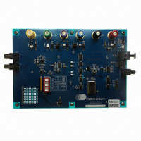
CDB5351
Description
EVALUATION BOARD FOR CS5351
Manufacturer
Cirrus Logic Inc
Specifications of CDB5351
Number Of Adc's
2
Number Of Bits
24
Sampling Rate (per Second)
192k
Data Interface
Serial
Inputs Per Adc
2 Single
Power (typ) @ Conditions
198mW @ 5 V
Voltage Supply Source
Analog and Digital
Operating Temperature
-10°C ~ 70°C
Utilized Ic / Part
CS5351
Product
Audio Modules
Lead Free Status / RoHS Status
Contains lead / RoHS non-compliant
Lead Free Status / RoHS Status
Lead free / RoHS Compliant, Contains lead / RoHS non-compliant
Other names
598-1781


18
4.4
4.5
Analog Connections
The analog modulator samples the input at 6.144 MHz. The digital filter will reject signals within the stop-
band of the filter. However, there is no rejection for input signals which are (n
band frequency, where n=0,1,2,...Refer to
noise energy at 6.144 MHz, in addition to providing the optimum source impedance for the modulators. The
use of capacitors which have a large voltage coefficient (such as general purpose ceramics) must be avoid-
ed since these can degrade signal linearity.
High-Pass Filter and DC Offset Calibration
The operational amplifiers in the input circuitry driving the CS5351 may generate a small DC offset into the
A/D converter. The CS5351 includes a high pass filter after the decimator to remove any DC offset which
could result in recording a DC level, possibly yielding "clicks" when switching between devices in a multi-
channel system.
The high pass filter continuously subtracts a measure of the DC offset from the output of the decimation
filter. If the HPF pin is taken high during normal operation, the current value of the DC offset register is frozen
and this DC offset will continue to be subtracted from the conversion result. This feature makes it possible
to perform a system DC offset calibration by:
Running the CS5351 with the high pass filter enabled until the filter settles. See the Digital Filter Character-
istics for filter settling time.
Disabling the high pass filter and freezing the stored DC offset.
A system calibration performed in this way will eliminate offsets anywhere in the signal path between the
calibration point and the CS5351.
100 kΩ
100 kΩ
1 μF
Figure 24. CS5351 Recommended Analog Input Buffer
1 μF
100 kΩ
100 kΩ
+
-
+
-
Figure 24
470 pF
470 pF
C0G
C0G
which shows the suggested filter that will attenuate any
634 Ω
634 Ω
91 Ω
91 Ω
-
+
1 μF
2700 pF
0.01 μF
2700 pF
C0G
C0G
×
6.144 MHz) the digital pass-
AINL
AINR
VQ1
VQ3
VQ2
CS5351
CS5351
DS565F2
Related parts for CDB5351
Image
Part Number
Description
Manufacturer
Datasheet
Request
R

Part Number:
Description:
Development Kit
Manufacturer:
Cirrus Logic Inc
Datasheet:
Part Number:
Description:
Development Kit
Manufacturer:
Cirrus Logic Inc
Datasheet:


Part Number:
Description:
High-efficiency PFC + Fluorescent Lamp Driver Reference Design
Manufacturer:
Cirrus Logic Inc
Datasheet:
Part Number:
Description:
Development Kit
Manufacturer:
Cirrus Logic Inc
Datasheet:
Part Number:
Description:
Development Kit
Manufacturer:
Cirrus Logic Inc
Datasheet:

Part Number:
Description:
Development Kit
Manufacturer:
Cirrus Logic Inc
Datasheet:
Part Number:
Description:
Development Kit
Manufacturer:
Cirrus Logic Inc
Datasheet:
Part Number:
Description:
Development Kit
Manufacturer:
Cirrus Logic Inc
Datasheet:
Part Number:
Description:
Development Kit
Manufacturer:
Cirrus Logic Inc
Datasheet:

Part Number:
Description:
EVALUATION BOARD FOR CS8427
Manufacturer:
Cirrus Logic Inc
Datasheet:

Part Number:
Description:
BOARD EVAL FOR CS8416 RCVR
Manufacturer:
Cirrus Logic Inc
Datasheet:

Part Number:
Description:
EVALUATION BOARD FOR CS8420
Manufacturer:
Cirrus Logic Inc
Datasheet:

Part Number:
Description:
KIT DEVELOPMENT EP9315 ARM9
Manufacturer:
Cirrus Logic Inc
Datasheet:

Part Number:
Description:
KIT DEVELOPMENT EP9302 ARM9
Manufacturer:
Cirrus Logic Inc
Datasheet: