CDB5560 Cirrus Logic Inc, CDB5560 Datasheet - Page 29
CDB5560
Manufacturer Part Number
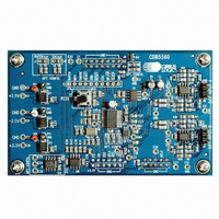
CDB5560
Description
DEV BOARD FOR CS5560 W/MUX
Manufacturer
Cirrus Logic Inc
Type
A/Dr
Specifications of CDB5560
Number Of Adc's
1
Number Of Bits
24
Sampling Rate (per Second)
50k
Data Interface
Serial
Inputs Per Adc
1 Differential
Input Range
±3 V
Power (typ) @ Conditions
90mW @ 2.5 V
Voltage Supply Source
Dual ±
Operating Temperature
-40°C ~ 85°C
Utilized Ic / Part
CS5560
Product
Data Conversion Development Tools
Conversion Rate
50 KSPS
Resolution
24 bit
Maximum Clock Frequency
16 MHz
Interface Type
SPI
Supply Voltage (max)
3.3 V
Supply Voltage (min)
- 2.5 V
For Use With/related Products
CS5560
Lead Free Status / RoHS Status
Contains lead / RoHS non-compliant
Lead Free Status / RoHS Status
Lead free / RoHS Compliant, Contains lead / RoHS non-compliant
Other names
598-1273
CDB5560-1
CDB5560-1


DS713PP2
VLR2, VLR, VL – Logic Interface Power/Return, Pins 14, 20, 21
SLEEP – Sleep Mode Select, Pin 12
BP/UP – Bipolar/Unipolar Select, Pin 11
CONV – Convert, Pin 15
MCLK – Master Clock, Pin 19
DCR – Digital Core Regulator, Pin 16
SDO – Serial Data Output, Pin 22
RST – Reset, Pin 13
V2+ – Positive Power 2, Pin 17
V2- – Negative Power 2, Pin 18
The BP/UP pin determines the span and the output coding of the converter. When set high to
select BP (bipolar), the input span of the converter is -4.096 volts to +4.096 volts fully differential
(assuming the voltage reference is 4.096 volts) and output data is coded in two's complement
format. When set low to select UP (unipolar), the input span is 0 to +4.096 fully differential and
the output data is coded in binary format.
When taken low, the SLEEP pin will cause the converter to enter into a low-power state. SLEEP
will stop the internal oscillator and power down all internal analog circuitry.
Reset is necessary after power is initially applied to the converter. When the RST input is taken
low, the logic in the converter will be reset. When RST is released to go high, certain portions of
the analog circuitry are started. RDY falls when reset is complete.
The CONV pin initiates a conversion cycle if taken low, unless a previous conversion is in
progress. When the conversion cycle is completed, the conversion word is output to the serial
port register and the RDY signal goes low. If CONV is held low and remains low when RDY
falls, another conversion cycle will be started.
DCR is the output of the on-chip regulator for the digital logic core. DCR should be bypassed
with a capacitor to V2-. The DCR pin is not designed to power any external load.
The V1+ and V2+ pins provide a positive supply voltage to the circuitry of the chip. These two
pins should be decoupled as shown in the application block diagrams. V1+ and V2+ should be
supplied from the same source voltage. For single-supply operation, these two voltages are
nominally +5 V. For dual-supply operation, they are nominally +2.5 V.
The V1- and V2- pins provide a negative supply voltage to the circuitry of the chip. These two
pins should be decoupled as shown in the application block diagrams. V1- and V2- should be
supplied from the same source voltage. For single-supply operation, these two voltages are
nominally 0 V (Ground). For dual-supply operation, they are nominally -2.5 V.
The master clock pin (MCLK) is a multi-function pin. If tied low (MCLK = VLR), the on-chip oscil-
lator will be enabled. If tied high (MCLK = VL), all clocks to the internal circuitry of the converter
will stop. When MCLK is held high the internal oscillator will also be stopped. MCLK can also
function as the input for an external CMOS-compatible clock that conforms to supply voltages
on the VL and VLR pins.
VL and VLR are the supply voltages for the digital logic interface. VL and VLR can be config-
ured with a wide range of common mode voltage. The following interface pins function from the
VL/VLR supply: SMODE, CS, SCLK, SDO, RDY, SLEEP, CONV, RST, BP/UP, and MCLK.
SDO is the output pin for the serial output port. Data from this pin will be output at a rate deter-
mined by SCLK and in a format determined by the BP/UP pin. Data is output MSB first and
advances to the next data bit on the rising edges of SCLK. SDO will be in a high impedance
state when CS is high.
5/4/09
CS5560
29
Related parts for CDB5560
Image
Part Number
Description
Manufacturer
Datasheet
Request
R

Part Number:
Description:
Development Kit
Manufacturer:
Cirrus Logic Inc
Datasheet:
Part Number:
Description:
Development Kit
Manufacturer:
Cirrus Logic Inc
Datasheet:


Part Number:
Description:
High-efficiency PFC + Fluorescent Lamp Driver Reference Design
Manufacturer:
Cirrus Logic Inc
Datasheet:
Part Number:
Description:
Development Kit
Manufacturer:
Cirrus Logic Inc
Datasheet:
Part Number:
Description:
Development Kit
Manufacturer:
Cirrus Logic Inc
Datasheet:

Part Number:
Description:
Development Kit
Manufacturer:
Cirrus Logic Inc
Datasheet:
Part Number:
Description:
Development Kit
Manufacturer:
Cirrus Logic Inc
Datasheet:
Part Number:
Description:
Development Kit
Manufacturer:
Cirrus Logic Inc
Datasheet:
Part Number:
Description:
Development Kit
Manufacturer:
Cirrus Logic Inc
Datasheet:

Part Number:
Description:
EVALUATION BOARD FOR CS8427
Manufacturer:
Cirrus Logic Inc
Datasheet:

Part Number:
Description:
BOARD EVAL FOR CS8416 RCVR
Manufacturer:
Cirrus Logic Inc
Datasheet:

Part Number:
Description:
EVALUATION BOARD FOR CS8420
Manufacturer:
Cirrus Logic Inc
Datasheet:

Part Number:
Description:
KIT DEVELOPMENT EP9315 ARM9
Manufacturer:
Cirrus Logic Inc
Datasheet:

Part Number:
Description:
KIT DEVELOPMENT EP9302 ARM9
Manufacturer:
Cirrus Logic Inc
Datasheet: