CDB35L00 Cirrus Logic Inc, CDB35L00 Datasheet - Page 6
CDB35L00
Manufacturer Part Number
CDB35L00
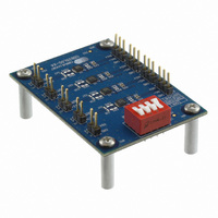
Description
DEVELOPMENT BOARD FOR CS35L0X
Manufacturer
Cirrus Logic Inc
Datasheet
1.CDB35L00.pdf
(12 pages)
Specifications of CDB35L00
Amplifier Type
Class D
Output Type
4-Channel (Quad)
Max Output Power X Channels @ Load
2.7W x 4 @ 4 Ohm
Voltage - Supply
2.5 V ~ 5.5 V
Board Type
Fully Populated
Utilized Ic / Part
CS35L0X
Description/function
Audio Amplifiers
Operating Supply Voltage
2.5 V to 5.5 V
Output Power
1.6 W, 2.7 W
Product
Audio Modules
For Use With/related Products
CS35L00
Lead Free Status / RoHS Status
Contains lead / RoHS non-compliant
Operating Temperature
-
Lead Free Status / Rohs Status
Lead free / RoHS Compliant
Other names
598-1803


6
1.6
1.7
1.7.1
Cut the bypass
traces before insert-
ing the optional
input gain adjust-
ment resistors
Differential Analog Inputs
The differential audio inputs into the four CS35L00 devices are provided by the 3-pin headers (J10, J20,
J30, and J40) through DC blocking capacitors (C11, C12, C21, C22, C31, C32, C41, C42). The DC blocking
capacitors allow for an analog source to connect directly to the CS35L00, regardless of any DC bias that
may be present between the analog audio source’s outputs and the CS35L00 inputs.
Speaker Outputs
The four CS35L00 power outputs pairs are each configured for a single, full-bridge, audio channel. The out-
puts are routed through an optional EMI output filter and then presented at the J11, J21, J31, and J41 head-
ers. The CS35L00 is intended to be used with a 4 to 8 load.
Optional Speaker Output EMI Filter Components
The CDB35L00-X4 contains optional placeholders for a series ferrite bead (FB11, FB12, FB21, FB22,
FB31, FB32, FB41, FB42) and shunt capacitor (C16, C17, C26, C27, C36, C37, C46, C47) output filter.
For most applications with very short speaker leads between the CS35L00 and the speaker, use of these
components will not be necessary. However, for systems with long signal paths between the CS35L00
and the speaker or if the system requires connecting to cables off the PCB, it is suggested that the ferrite
bead and capacitor are populated with the recommended values shown in
tional output filters will reduce EMI between the CS35L00 speaker outputs and the load.
In order to use the optional output filter ferrite beads for U1, the traces between the FB11 pads and the
traces between the FB12 pads must be cut to break the bypass circuit, before populating FB11 and FB12
with the desired component values. The location of these required cuts are shown in below in
The optional output filter ferrite beads for U2, U3, and U4 can be added in the same manner as described
for U1 (above). The optional output filter capacitors can be populated with or without the addition of the
ferrite beads and require no board modifications.
Figure 3. Optional Bypass Trace Cut Locations for U1
Table 6 on page
CDB35L00-X4
Cut the bypass
traces before
inserting the
optional output fil-
ter ferrite beads
10. These op-
DS913DB2
Figure
3.
Related parts for CDB35L00
Image
Part Number
Description
Manufacturer
Datasheet
Request
R

Part Number:
Description:
Audio Modules & Development Tools Eval Bd - DF 4ch ADC 8ch DAC & 32bit DSP
Manufacturer:
Cirrus Logic Inc
Part Number:
Description:
Development Kit
Manufacturer:
Cirrus Logic Inc
Datasheet:
Part Number:
Description:
Development Kit
Manufacturer:
Cirrus Logic Inc
Datasheet:


Part Number:
Description:
High-efficiency PFC + Fluorescent Lamp Driver Reference Design
Manufacturer:
Cirrus Logic Inc
Datasheet:
Part Number:
Description:
Development Kit
Manufacturer:
Cirrus Logic Inc
Datasheet:
Part Number:
Description:
Development Kit
Manufacturer:
Cirrus Logic Inc
Datasheet:

Part Number:
Description:
Development Kit
Manufacturer:
Cirrus Logic Inc
Datasheet:
Part Number:
Description:
Development Kit
Manufacturer:
Cirrus Logic Inc
Datasheet:
Part Number:
Description:
Development Kit
Manufacturer:
Cirrus Logic Inc
Datasheet:

Part Number:
Description:
EVALUATION BOARD FOR CS8427
Manufacturer:
Cirrus Logic Inc
Datasheet:

Part Number:
Description:
BOARD EVAL FOR CS8416 RCVR
Manufacturer:
Cirrus Logic Inc
Datasheet:

Part Number:
Description:
EVALUATION BOARD FOR CS8420
Manufacturer:
Cirrus Logic Inc
Datasheet:

Part Number:
Description:
KIT DEVELOPMENT EP9315 ARM9
Manufacturer:
Cirrus Logic Inc
Datasheet:

Part Number:
Description:
KIT DEVELOPMENT EP9302 ARM9
Manufacturer:
Cirrus Logic Inc
Datasheet: