EVL6566B-40WSTB STMicroelectronics, EVL6566B-40WSTB Datasheet - Page 36
EVL6566B-40WSTB
Manufacturer Part Number
EVL6566B-40WSTB
Description
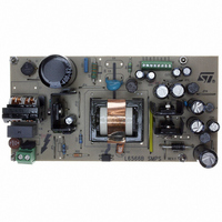
BOARD EVAL FOR L6566B
Manufacturer
STMicroelectronics
Datasheet
1.L6566BTR.pdf
(51 pages)
Specifications of EVL6566B-40WSTB
Main Purpose
AC/DC, Primary Side
Outputs And Type
4, Isolated
Power - Output
40W
Voltage - Output
5V, 12V, 1.8V, 3.3V
Current - Output
2.4A, 1.9A, 1.73A, 500mA
Voltage - Input
90 ~ 264VAC
Regulator Topology
Flyback
Frequency - Switching
62kHz
Board Type
Fully Populated
Utilized Ic / Part
L6566B
Product
Power Management Modules
Lead Free Status / RoHS Status
Lead free / RoHS Compliant
Other names
497-6450
Available stocks
Company
Part Number
Manufacturer
Quantity
Price


Application information
Note:
36/51
Figure 23. OVP function: timing diagram
The value of R
capability of the internal clamp:
Equation 14
where Vin
winding. See
page 21
To reduce sensitivity to noise and prevent the latch from being erroneously activated, first
the OVP comparator is active only for a small time window (typically, 0.5 µs) starting 2 µs
after MOSFET’s turn-off, to reject the voltage spike associated to the positive-going edges
of the voltage across the auxiliary winding Vaux; second, to stop the L6566B the OVP
comparator must be triggered for four consecutive switching cycles. A counter, which is
reset every time the OVP comparator is not triggered in one switching cycle, is provided to
this purpose.
Figure 22 on page 35
Figure 23
To use the OVP function effectively, i.e. to ensure that the OVP comparator will be always
interrogated during MOSFET’s OFF-time, the duty cycle D under open-loop conditions must
fulfill the following inequality:
COUNTER
COUNTER
STATUS
RESET
STROBE
(pin 11)
(pin 4)
FAULT
COUT
ZCD
GD
Vaux
5V
OVP
0
for additional details.
0
max
illustrate the operation.
NORMAL OPERATION
Section 5.2: Zero current detection and triggering block; oscillator block on
is the maximum dc input voltage and Ns the turn number of the primary
2 µs
Z1
0
will be such that the current sourced by the ZCD pin be within the rated
shows the internal block diagram, while the timing diagrams in
0.5 µs
0
0 → 1
TEMPORARY DISTURBANCE
R
Z
1
≥
1 → 2
3
⋅
10
1
−
2 → 0
3
Naux
Np
0
Vin
max
0 → 1
FEEDBACK LOOP FAILURE
1 → 2
2 → 3
3 → 4
L6566B
t
t
t
t
t
t
t
t
t
Related parts for EVL6566B-40WSTB
Image
Part Number
Description
Manufacturer
Datasheet
Request
R

Part Number:
Description:
BOARD EVAL SMPS FOR L6566B
Manufacturer:
STMicroelectronics
Datasheet:

Part Number:
Description:
BOARD EVAL FOR L6566B
Manufacturer:
STMicroelectronics
Datasheet:

Part Number:
Description:
BOARD EVAL FOR L6566B
Manufacturer:
STMicroelectronics
Datasheet:

Part Number:
Description:
Power Management Modules & Development Tools L6566B-60WQR Eval Board
Manufacturer:
STMicroelectronics
Part Number:
Description:
STMicroelectronics [RIPPLE-CARRY BINARY COUNTER/DIVIDERS]
Manufacturer:
STMicroelectronics
Datasheet:
Part Number:
Description:
STMicroelectronics [LIQUID-CRYSTAL DISPLAY DRIVERS]
Manufacturer:
STMicroelectronics
Datasheet:

Part Number:
Description:
BOARD EVAL FOR MEMS SENSORS
Manufacturer:
STMicroelectronics
Datasheet:
Part Number:
Description:
NPN TRANSISTOR POWER MODULE
Manufacturer:
STMicroelectronics
Datasheet:
Part Number:
Description:
TURBOSWITCH ULTRA-FAST HIGH VOLTAGE DIODE
Manufacturer:
STMicroelectronics
Datasheet:
Part Number:
Description:
Manufacturer:
STMicroelectronics
Datasheet:
Part Number:
Description:
DIODE / SCR MODULE
Manufacturer:
STMicroelectronics
Datasheet:
Part Number:
Description:
DIODE / SCR MODULE
Manufacturer:
STMicroelectronics
Datasheet: