EVAL-AD5764EBZ Analog Devices Inc, EVAL-AD5764EBZ Datasheet
EVAL-AD5764EBZ
Specifications of EVAL-AD5764EBZ


Related parts for EVAL-AD5764EBZ


EVAL-AD5764EBZ Summary of contents
Page 1
FEATURES Complete quad, 16-bit digital-to-analog converter (DAC) Programmable output range ±10 V, ±10.2564 V, or ±10.5263 V ±1 LSB maximum INL error, ±1 LSB maximum DNL error Low noise: 60 nV/√Hz Settling time: 10 μs maximum Integrated reference buffers Output ...
Page 2
... Typical Operating Circuit ......................................................... 25 Layout Guidelines ........................................................................... 27 Galvanically Isolated Interface ................................................. 27 Microprocessor Interfacing ....................................................... 27 Evaluation Board ........................................................................ 27 Outline Dimensions ....................................................................... 28 Ordering Guide .......................................................................... 28 04/08—Rev Rev. B Changes to Table Summary Statement, Specifications Section ... 4 Changes to Power Requirements Parameter, Table 2 and Table Summary Statement ................................................................ 5 Changes to t Parameter, Table 4 ...
Page 3
FUNCTIONAL BLOCK DIAGRAM AV AV PGND AD5764 DGND 16 SDIN INPUT SHIFT SCLK REGISTER AND SYNC CONTROL LOGIC SDO D0 D1 BIN/2sCOMP CLR AV AV REFGND DD SS REFERENCE 16 INPUT DATA REG A REG A ...
Page 4
AD5764 SPECIFICATIONS −11 −16.5 V, AGNDx = DGND = REFGND = PGND = 0 V; REFAB = REFCD = 2 5.25 ...
Page 5
Parameter 1 DIGITAL OUTPUTS (D0, D1, SDO) Output Low Voltage Output High Voltage Output Low Voltage Output High Voltage High Impedance Leakage Current High Impedance Output Capacitance POWER REQUIREMENTS AV / Power Supply Sensitivity ∆V ...
Page 6
AD5764 TIMING CHARACTERISTICS −11 −16.5 V, AGNDx = DGND = REFGND = PGND = 0 V; REFAB = REFCD = 2 ...
Page 7
Timing Diagrams SCLK SYNC t 7 SDIN DB23 LDAC VOUTx LDAC = 0 VOUTx CLR VOUTx SCLK SYNC t 7 DB23 SDIN SDO LDAC ...
Page 8
AD5764 SCLK SYNC DB23 SDIN SDO 24 DB0 DB23 INPUT WORD SPECIFIES REGISTER TO BE READ DB23 UNDEFINED Figure 4. Readback Timing Diagram 200µ SDO OH PIN 50pF 200µ Figure ...
Page 9
ABSOLUTE MAXIMUM RATINGS T = 25°C, unless otherwise noted. Transient currents 100 mA do not cause SCR latch-up. Table 5. Parameter AV to AGNDx, DGND AGNDx, DGND DGND CC Digital ...
Page 10
AD5764 PIN CONFIGURATION AND FUNCTION DESCRIPTIONS Table 6. Pin Function Descriptions Pin No. Mnemonic Description 1 SYNC Active Low Input. This is the frame synchronization signal for the serial interface. While SYNC is low, data is transferred in on the ...
Page 11
Pin No. Mnemonic Description 21 AGNDB Ground Reference Pin for DAC B Output Amplifier. 22 VOUTB Analog Output Voltage of DAC B. Buffered output with a nominal full-scale output range of ±10 V. The output amplifier is capable of directly ...
Page 12
AD5764 TYPICAL PERFORMANCE CHARACTERISTICS 1.0 0.8 0.6 0.4 0.2 0 –0.2 –0.4 –0.6 –0.8 –1.0 0 10000 20000 30000 40000 DAC CODE Figure 7. Integral Nonlinearity Error vs. Code, AV /AV = ± 1 25°C ...
Page 13
T = 25°C A –0.20 AV /AV = ±15V REFIN –0.25 –40 – TEMPERATURE (°C) Figure 13. Differential Nonlinearity Error vs. Temperature, AV /AV ...
Page 14
AD5764 0 25°C A 0.4 AV /AV = ±16. 0.2 0 –0.2 –0.4 –0.6 –0.8 –1.0 –1.2 –1.4 –1 REFERENCE VOLTAGE (V) Figure 19. Total Unadjusted Error vs. Reference Voltage, AV /AV ...
Page 15
T = 25° REFIN 6000 RI = 6kΩ SCC AV /AV DD 5000 AV /AV DD 4000 3000 2000 1000 0 –1000 –10 – SOURCE/SINK CURRENT (mA) Figure 25. Source and Sink Capability ...
Page 16
AD5764 AV /AV = ±15V DD SS MIDSCALE LOADED REFIN 4 CH4 50.0µV M1.00s Figure 29. Peak-to-Peak Noise (100 kHz Bandwidth REFIN 25° RAMP TIME = 100µs LOAD ...
Page 17
TERMINOLOGY Relative Accuracy or Integral Nonlinearity (INL) For the DAC, relative accuracy or integral nonlinearity (INL measure of the maximum deviation, in LSBs, from a straight line passing through the endpoints of the DAC transfer function. A typical ...
Page 18
AD5764 THEORY OF OPERATION The AD5764 is a quad, 16-bit, serial input, bipolar voltage output DAC and operates from supply voltages of ±11 ±16.5 V and has a buffered output voltage ±10.5263 V. Data is ...
Page 19
Daisy-Chain Operation 1 68HC11 MOSI SDIN SCK SCLK PC7 SYNC PC6 LDAC MISO SCLK SYNC LDAC SCLK SYNC LDAC 1 ADDITIONAL PINS OMITTED FOR CLARITY Figure 33. Daisy-Chaining the AD5764 For systems that contain several devices, the SDO pin can ...
Page 20
AD5764 TRANSFER FUNCTION Table 7 and Table 8 show the ideal input code to output voltage relationship for the AD5764 for both offset binary and twos complement data coding, respectively. Table 7. Ideal Output Voltage to Input Code Relationship— Offset ...
Page 21
FUNCTION REGISTER The function register is addressed by setting the three REG bits to 000. The values written to the address bits and the data bits determine the function addressed. The functions available via the function register are outlined in ...
Page 22
AD5764 FINE GAIN REGISTER The fine gain register is addressed by setting the three REG bits to 100. The DAC address bits select with which DAC channel the data transfer is to take place (see Table 10). The fine gain ...
Page 23
OFFSET AND GAIN ADJUSTMENT WORKED EXAMPLE Using the information provided in the Fine Gain Register and Offset Register sections, the following worked example demon- strates how the AD5764 functions can be used to eliminate both offset and gain errors. Because ...
Page 24
AD5764 DESIGN FEATURES ANALOG OUTPUT CONTROL In many industrial process control applications vital that the output voltage be controlled during power-up and during brownout conditions. When the supply voltages are changing, the VOUTx pins are clamped to 0 ...
Page 25
APPLICATIONS INFORMATION TYPICAL OPERATING CIRCUIT Figure 36 shows the typical operating circuit for the AD5764. The only external components needed for this precision 16-bit DAC are a reference voltage source, decoupling capacitors on the supply pins and reference inputs, and ...
Page 26
AD5764 Precision Voltage Reference Selection To achieve the optimum performance from the AD5764 over its full operating temperature range, a precision voltage reference must be used. Consideration should be given to the selection of a precision voltage reference. The AD5764 ...
Page 27
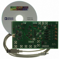
... The AD5764 comes with a full evaluation board to aid designers in evaluating the high performance of the part with minimum effort. All that is required with the evaluation board is a power supply and a PC. The AD5764 evaluation kit includes a populated, tested AD5764 PCB. The evaluation board interfaces to the USB port of the PC ...
Page 28
... LSB max 1 AD5764BSUZ-REEL7 ±2 LSB max 1 AD5764CSUZ ±1 LSB max AD5764CSUZ-REEL7 1 ±1 LSB max 1 EVAL-AD5764EBZ RoHS Compliant Part. ©2006–2009 Analog Devices, Inc. All rights reserved. Trademarks and registered trademarks are the property of their respective owners. 1.20 0.75 MAX 0.60 0. 0° ...