SSL2101T/DB/FBCB120V,598 NXP Semiconductors, SSL2101T/DB/FBCB120V,598 Datasheet - Page 7
SSL2101T/DB/FBCB120V,598
Manufacturer Part Number
SSL2101T/DB/FBCB120V,598
Description
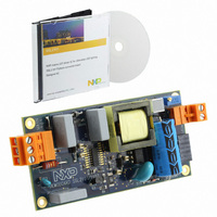
BOARD EVAL LED DRIVER SS2101
Manufacturer
NXP Semiconductors
Type
DC/DC Switching Converters, Regulators & Controllersr
Specifications of SSL2101T/DB/FBCB120V,598
Current - Output / Channel
400 mA ~ 800 mA
Outputs And Type
1, Isolated
Voltage - Output
9 ~ 23 V
Features
Dimmable, TRIAC Dimmable
Voltage - Input
120VAC
Utilized Ic / Part
SSL2101
Input Voltage
120 V
Board Size
103 mm x 50 mm x 20 mm
Maximum Operating Temperature
+ 100 C
Minimum Operating Temperature
- 40 C
Operating Supply Voltage
8.5 V to 40 V
Product
Power Management Modules
Dimensions
103 mm x 50 mm x 20 mm
For Use With/related Products
SSL2101T
Lead Free Status / RoHS Status
Lead free / RoHS Compliant
Lead Free Status / RoHS Status
Lead free / RoHS Compliant, Lead free / RoHS Compliant
Other names
568-4812


NXP Semiconductors
SSL2101_4
Product data sheet
8.4 Bleeder for dimming applications
8.5 Valley switching
The SSL2101 IC contains some circuitry intended for mains dimmer compatibility. This
circuit contains two current sinks that are called bleeders. A strong bleeder is used for
zero-cross reset of the dimmer and triac latching. A weak bleeder is added to maintain the
hold current through the dimmer.
The strong bleeder switch is switched on when the maximum voltage on pin WBLEED and
SBLEED is below the V
switched on as soon as the voltage on pin ISENSE exceeds the V
( 100 mV typically). The weak bleeder switch is switched off when the ISENSE voltage
drops below the V
switched off when the strong bleeder switch is switched on. See
A new cycle is started when the primary switch is switched on (see
determined by the oscillator voltage, RC and the internal regulation level, the switch is
turned off and the secondary stroke starts. The internal regulation level is determined by
the voltage on pin PWMLIMIT.
After the secondary stroke, the drain voltage shows an oscillation with a frequency of
approximately:
where:
---------------------------------------------- -
2
Fig 5.
L
C
p
p
= primary self inductance
= parasitic capacitance on drain node
1
Bleeder circuit
L
p
C
p
th(low)(ISENSE)
WBLEED
ISENSE
Rev. 04 — 28 August 2009
0.25 V
th(SBLEED)
M2
0.1 V
level ( 250 mV typically). The weak bleeder switch is also
D2
S
level (52 V typically). The weak bleeder switch is
Q
R
B1
LOW V DETECT
OR
I1
20 A
SMPS IC for dimmable LED lighting
D3
SBLEED
M1
GND
014aaa571
Integrated
Figure
th(high)(ISENSE)
Figure
SSL2101
© NXP B.V. 2009. All rights reserved.
5.
6). After a time
level
7 of 22
(2)
Related parts for SSL2101T/DB/FBCB120V,598
Image
Part Number
Description
Manufacturer
Datasheet
Request
R

Part Number:
Description:
BOARD EVAL LED DRIVER SS2101
Manufacturer:
NXP Semiconductors
Datasheet:

Part Number:
Description:
NXP Semiconductors designed the LPC2420/2460 microcontroller around a 16-bit/32-bitARM7TDMI-S CPU core with real-time debug interfaces that include both JTAG andembedded trace
Manufacturer:
NXP Semiconductors
Datasheet:

Part Number:
Description:
NXP Semiconductors designed the LPC2458 microcontroller around a 16-bit/32-bitARM7TDMI-S CPU core with real-time debug interfaces that include both JTAG andembedded trace
Manufacturer:
NXP Semiconductors
Datasheet:
Part Number:
Description:
NXP Semiconductors designed the LPC2468 microcontroller around a 16-bit/32-bitARM7TDMI-S CPU core with real-time debug interfaces that include both JTAG andembedded trace
Manufacturer:
NXP Semiconductors
Datasheet:
Part Number:
Description:
NXP Semiconductors designed the LPC2470 microcontroller, powered by theARM7TDMI-S core, to be a highly integrated microcontroller for a wide range ofapplications that require advanced communications and high quality graphic displays
Manufacturer:
NXP Semiconductors
Datasheet:
Part Number:
Description:
NXP Semiconductors designed the LPC2478 microcontroller, powered by theARM7TDMI-S core, to be a highly integrated microcontroller for a wide range ofapplications that require advanced communications and high quality graphic displays
Manufacturer:
NXP Semiconductors
Datasheet:
Part Number:
Description:
The Philips Semiconductors XA (eXtended Architecture) family of 16-bit single-chip microcontrollers is powerful enough to easily handle the requirements of high performance embedded applications, yet inexpensive enough to compete in the market for hi
Manufacturer:
NXP Semiconductors
Datasheet:
Part Number:
Description:
The XA-S3 device is a member of Philips Semiconductors? XA(eXtended Architecture) family of high performance 16-bitsingle-chip microcontrollers
Manufacturer:
NXP Semiconductors
Datasheet:

Part Number:
Description:
The NXP BlueStreak LH75401/LH75411 family consists of two low-cost 16/32-bit System-on-Chip (SoC) devices
Manufacturer:
NXP Semiconductors
Datasheet:
Part Number:
Description:
The NXP LPC3130/3131 combine an 180 MHz ARM926EJ-S CPU core, high-speed USB2
Manufacturer:
NXP Semiconductors
Datasheet:
Part Number:
Description:
The NXP LPC3141 combine a 270 MHz ARM926EJ-S CPU core, High-speed USB 2
Manufacturer:
NXP Semiconductors
Part Number:
Description:
The NXP LPC3143 combine a 270 MHz ARM926EJ-S CPU core, High-speed USB 2
Manufacturer:
NXP Semiconductors

Part Number:
Description:
The NXP LPC3152 combines an 180 MHz ARM926EJ-S CPU core, High-speed USB 2
Manufacturer:
NXP Semiconductors
Part Number:
Description:
The NXP LPC3154 combines an 180 MHz ARM926EJ-S CPU core, High-speed USB 2
Manufacturer:
NXP Semiconductors