NCP3065D3SLDGEVB ON Semiconductor, NCP3065D3SLDGEVB Datasheet
NCP3065D3SLDGEVB
Manufacturer Part Number
NCP3065D3SLDGEVB
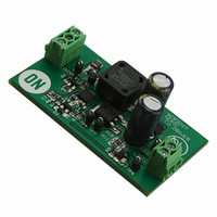
Description
EVAL BOARD FOR NCP3065D3SLDG
Manufacturer
ON Semiconductor
Datasheets
1.NCP3065DR2G.pdf
(18 pages)
2.NCP3065D3SLDGEVB.pdf
(1 pages)
3.NCP3065D3SLDGEVB.pdf
(11 pages)
Specifications of NCP3065D3SLDGEVB
Design Resources
NCP3065D3SLDGEVB BOM NCP3065D3SLDGEVB Gerber Files NCP3065D3SLDGEVB Schematic
Current - Output / Channel
700mA
Outputs And Type
1, Non-Isolated
Voltage - Output
7 ~ 23 V
Voltage - Input
12V
Utilized Ic / Part
NCP3065
Core Chip
NCP3065
Topology
SEPIC
No. Of Outputs
1
Output Current
1A
Output Voltage
23V
Dimming Control Type
PWM
Development Tool Type
Hardware - Eval/Demo Board
Leaded Process Compatible
Yes
Rohs Compliant
Yes
Lead Free Status / RoHS Status
Lead free / RoHS Compliant
Features
-
Lead Free Status / Rohs Status
Lead free / RoHS Compliant
For Use With/related Products
NCP3065D3SLDG
Other names
NCP3065D3SLDGEVBOS
Test Procedure for the NCP3065 High Brightness LED SEPIC Driver
11/10/2007
DC Power
V
Supply
A
A
DC El. LOAD
V
Figure 1: Test Setup
The following steps detail the test procedure for all these boards:
Required Equipment:
Current limited DC Power Supply (e.g. AGILENT 6653A) … 1pcs
DC Volt-Meter able to measure up to 30V DC (e.g. KEITHLEY 2000) … 2pcs
DC Amp-Meter able to measure up to 2A DC (e.g. KEITHLEY 2000) … 2pcs
DC Electronic Load (e.g. AGILENT 6060B) … 1pcs
Test Procedure:
1. Connect the test setup as shown in Figure 1.
2. Apply an input voltage, Uin = 12Vdc
3. Apply Iout(load) = 0A
4. Check that Uout is approximately 26Vdc
5. Set Vout-load (load in voltage mode) to: 7 to 23Vdc
6. Check that Iout is approximately 350mA or 700mA
7. Power down the load
8. Power down Uin
9. End of test
Related parts for NCP3065D3SLDGEVB
Image
Part Number
Description
Manufacturer
Datasheet
Request
R

Part Number:
Description:
Up to 1.5 A Constant Current Switching Regulator for LEDs
Manufacturer:
ON Semiconductor
Datasheet:

Part Number:
Description:
EVAL BOARD FOR NCP3065SOBCKG
Manufacturer:
ON Semiconductor
Datasheet:

Part Number:
Description:
EVAL BOARD FOR NCP3065SOBSTG
Manufacturer:
ON Semiconductor
Datasheet:

Part Number:
Description:
EVAL BOARD FOR NCP30653ABCKG
Manufacturer:
ON Semiconductor
Datasheet:
Part Number:
Description:
ON Semiconductor [VOLTAGE REGULATOR]
Manufacturer:
ON Semiconductor
Datasheet:
Part Number:
Description:
357-036-542-201 CARDEDGE 36POS DL .156 BLK LOPRO
Manufacturer:
ON Semiconductor
Datasheet:
Part Number:
Description:
357-036-542-201 CARDEDGE 36POS DL .156 BLK LOPRO
Manufacturer:
ON Semiconductor
Datasheet:
Part Number:
Description:
357-036-542-201 CARDEDGE 36POS DL .156 BLK LOPRO
Manufacturer:
ON Semiconductor
Datasheet:
Part Number:
Description:
357-036-542-201 CARDEDGE 36POS DL .156 BLK LOPRO
Manufacturer:
ON Semiconductor
Datasheet:
Part Number:
Description:
357-036-542-201 CARDEDGE 36POS DL .156 BLK LOPRO
Manufacturer:
ON Semiconductor
Datasheet:
Part Number:
Description:
357-036-542-201 CARDEDGE 36POS DL .156 BLK LOPRO
Manufacturer:
ON Semiconductor
Datasheet:
Part Number:
Description:
357-036-542-201 CARDEDGE 36POS DL .156 BLK LOPRO
Manufacturer:
ON Semiconductor
Datasheet:
Part Number:
Description:
357-036-542-201 CARDEDGE 36POS DL .156 BLK LOPRO
Manufacturer:
ON Semiconductor
Datasheet:
Part Number:
Description:
357-036-542-201 CARDEDGE 36POS DL .156 BLK LOPRO
Manufacturer:
ON Semiconductor
Datasheet:
Part Number:
Description:
357-036-542-201 CARDEDGE 36POS DL .156 BLK LOPRO
Manufacturer:
ON Semiconductor
Datasheet: