NCP3065D3SLDGEVB ON Semiconductor, NCP3065D3SLDGEVB Datasheet
NCP3065D3SLDGEVB
Specifications of NCP3065D3SLDGEVB


Related parts for NCP3065D3SLDGEVB


NCP3065D3SLDGEVB Summary of contents
Page 1
Device Application Solid State, NCP3065 Automotive and NCV3065 Marine Lighting Output Voltage Current Ripple Nominal Current Max Current Min Current Minimum Efficiency Circuit Description This circuit is intended for driving high power LEDs, such as the Cree XLAMP™ series, Lumileds ...
Page 2
Schematic Design Notes A SEPIC (single-ended primary inductance converter) is distinguished by the fact that its input voltage range can overlap the output voltage range. The basic schematic is shown in Figure 2. When switch SW is ON, energy from ...
Page 3
For a 0.35 A output current variant of this circuit, the values of inductors are The nearest coupled inductor value for the 0.7 A variant is 15 μH. A variant with 0.35 A output current needs to use inductors with ...
Page 4
The C4 coupling capacitor is selected based on input voltage and on current RMS and its minimal value is The output capacitor’s current is > The value could be much larger for ...
Page 5
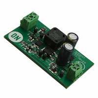
PC Board November 2007, Rev.2 DN06031/D Figure 3 – components position on PCB Figure 4 – PCB’s top side www.onsemi.com 5 ...
Page 6
November 2007, Rev.2 DN06031/D Figure 5 – PCB’s bottom side www.onsemi.com 6 ...
Page 7
November 2007, Rev.2 DN06031/D www.onsemi.com 7 ...
Page 8
Measurements NCP3065 SEPIC Converter - Line regulation, I 0,400 0,390 0,380 0,370 0,360 0,350 0,340 0,330 0,320 0,310 0,300 NCP3065 SEPIC Converter - Efficiency November ...
Page 9
NCP3065 SEPIC Converter - Line regulation, I 0,800 0,780 0,760 0,740 0,720 0,700 0,680 0,660 0,640 0,620 0,600 NCP3065 SEPIC Converter - Efficiency November 2007, Rev.2 ...
Page 10
NCP3065 SEPIC Converter - Dimming Linearity 700 600 500 400 300 200 100 Figure 10 – Dimming linearity, dimming frequency 200Hz November 2007, Rev.2 DN06031 D[%] Figure 11 – PCB’s top side www.onsemi.com ...
Page 11
... Disclaimer: ON Semiconductor is providing this design note “AS IS” and does not assume any liability arising from its use; nor does ON Semiconductor convey any license to its or any third party’s intellectual property rights. This document is provided only to assist customers in evaluation of the referenced circuit implementation and the recipient assumes all liability and risk associated with its use, including, but not limited to, compliance with all regulatory standards ...