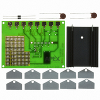
EK11 Cirrus Logic Inc, EK11 Datasheet

EK11
Specifications of EK11
EK11
Related parts for EK11
EK11 Summary of contents
Page 1
...
Page 2
PA90 1. CHARACTERISTICS AND SPECIFICATIONS ABSOLUTE MAXIMUM RATINGS Parameter SUPPLY VOLTAGE OUTPUT CURRENT, source, sink, peak, within SOA POWER DISSIPATION, continuous @ T INPUT VOLTAGE, differential INPUT VOLTAGE, common mode TEMPERATURE, pin solder, 10s max. TEMPERATURE, junction (Note 2) TEMPERATURE RANGE, storage OPERATING TEMPERATURE RANGE, case The PA90 is constructed from MOSFET transistors. ESD handling procedures must be observed. CAUTION The exposed substrate contains beryllia (BeO). Do not crush, machine, or subject to temperatures in excess of 850°C to avoid generating toxic fumes. SPECIFICATIONS Parameter AMPLIFIER INPUT OFFSET VOLTAGE, initial OFFSET VOLTAGE vs. temperature OFFSET VOLTAGE vs. supply OFFSET VOLTAGE vs. time BIAS CURRENT, initial BIAS CURRENT vs. supply OFFSET CURRENT, initial INPUT IMPEDANCE, DC INPUT CAPACITANCE ...
Page 3
Parameter SETTLING TIME to 0.1% RESISTANCE, no load POWER SUPPLY VOLTAGE (Note 5) CURRENT, quiescent THERMAL RESISTANCE, AC, junction to case (Note 4) Full temp range, F > 60Hz RESISTANCE, DC, junction to case RESISTANCE, junction to air TEMPERATURE RANGE, case NOTES: 1. (All Min/Max characteristics and specifications are guaranteed over the Specified Operating Condi- tions. Typical performance characteristics and specifications are derived from measurements taken at typical supply voltages and T ...
Page 4
PA90 100 125 150 CASE TEMPERATURE, T (°C) C SMALL SIGNAL RESPONSE 4 ...
Page 5
SAFE OPERATING AREA (SOA) The MOSFET output stage of this power operational amplifier has two distinct limitations: 1. The current handling capability of the MOSFET geometry and the wire bonds. 2. The junction temperature of the output MOSFETs. NOTE: The output stage is protected against transient flyback. However, for protection against sustained, high en- ergy flyback, external fast-recovery diodes should be used. SAFE OPERATING CURVES The safe operating area curves define the maximum ad- ditional internal power dissipation the amplifier can toler- ate when it ...
Page 6
PA90 CONTACTING CIRRUS LOGIC SUPPORT For all Apex Precision Power product questions and inquiries, call toll free 800-546-2739 in North America. For inquiries via email, please contact apex.support@cirrus.com. International customers can also request support by contacting their local Cirrus Logic Sales Representative. To find the one nearest to you www.cirrus.com IMPORTANT NOTICE Cirrus Logic, Inc. and its subsidiaries ("Cirrus") believe that the information contained in this document is accurate and reliable. However, the information is subject to change without notice and is provided "AS IS" without warranty of any kind (express or implied). Customers are advised to obtain the latest version of relevant information to verify, before placing orders, that information being relied on is current and complete. All products are sold subject to the terms and conditions of sale supplied at the time of order acknowledgment, including those pertaining to warranty, indemnification, and limitation of liability. No responsibility is assumed by Cirrus for the use of this information, including use of this information as the basis for manufacture or sale of any items, or for infringement of patents or other rights of third parties. This document is the property of Cirrus and by furnishing this information, Cirrus grants no license, express or implied under any patents, mask work rights, copyrights, trademarks, trade secrets or other intellectual property rights. Cirrus owns the copyrights associated with the information contained herein and gives con- sent for copies to be made of the information only for use within your organization with respect to Cirrus integrated circuits or other products of Cirrus. This consent does not extend to other copying such as copying for general distribution, advertising or promotional purposes, or for creating any work for resale. CERTAIN APPLICATIONS USING SEMICONDUCTOR PRODUCTS MAY INVOLVE POTENTIAL RISKS OF DEATH, PERSONAL INJURY, OR SEVERE PROP- ERTY OR ENVIRONMENTAL DAMAGE (“CRITICAL APPLICATIONS”). CIRRUS PRODUCTS ARE NOT DESIGNED, AUTHORIZED OR WARRANTED TO BE SUITABLE FOR USE IN PRODUCTS SURGICALLY IMPLANTED INTO THE BODY, AUTOMOTIVE SAFETY OR SECURITY DEVICES, LIFE SUPPORT PROD- UCTS OR OTHER CRITICAL APPLICATIONS. INCLUSION OF CIRRUS PRODUCTS IN SUCH APPLICATIONS IS UNDERSTOOD TO BE FULLY AT THE CUS- TOMER’S RISK AND CIRRUS DISCLAIMS AND MAKES NO WARRANTY, EXPRESS, STATUTORY OR IMPLIED, INCLUDING THE IMPLIED WARRANTIES OF MERCHANTABILITY AND FITNESS FOR PARTICULAR PURPOSE, WITH REGARD TO ANY CIRRUS PRODUCT THAT IS USED IN SUCH A MANNER. IF THE CUSTOMER OR CUSTOMER’S CUSTOMER USES OR PERMITS THE USE OF CIRRUS PRODUCTS IN CRITICAL APPLICATIONS, CUSTOMER AGREES, BY SUCH USE, TO FULLY INDEMNIFY CIRRUS, ITS OFFICERS, DIRECTORS, EMPLOYEES, DISTRIBUTORS AND OTHER AGENTS FROM ANY AND ALL LIABILITY, INCLUDING ATTORNEYS’ FEES AND COSTS, THAT MAY RESULT FROM OR ARISE IN CONNECTION WITH THESE USES. Cirrus Logic, Cirrus, and the Cirrus Logic logo designs, Apex Precision Power, Apex and the Apex Precision Power logo designs are trademarks of Cirrus Logic, Inc. All other brand and product names in this document may be trademarks or service marks of their respective owners ...


