EK11 Cirrus Logic Inc, EK11 Datasheet - Page 3
EK11
Manufacturer Part Number
EK11
Description
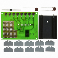
KIT EVALUATION PA90 PA91 PA98
Manufacturer
Cirrus Logic Inc
Series
Apex Precision Power™r
Specifications of EK11
Channels Per Ic
1 - Single
Amplifier Type
Power
Output Type
Single-Ended
Board Type
Bare (Unpopulated)
Utilized Ic / Part
PA90, PA91, PA98
Product
Amplifier Modules
Description/function
Audio Amplifiers
Lead Free Status / RoHS Status
Contains lead / RoHS non-compliant
Operating Temperature
-
Current - Output / Channel
-
Voltage - Supply, Single/dual (±)
-
-3db Bandwidth
-
Slew Rate
-
Current - Supply (main Ic)
-
Lead Free Status / RoHS Status
Lead free / RoHS Compliant, Contains lead / RoHS non-compliant
Other names
598-1458
EK11
EK11


NOTES: 1. (All Min/Max characteristics and specifications are guaranteed over the Specified Operating Condi-
TYPICAL APPLICATION
LOW POWER, PIEZOELECTRIC POSITIONING
Piezo positioning may be applied to the focusing of segment-
ed mirror systems. The composite mirror may be composed
of hundreds of elements, each requiring focusing under com-
puter control. In such complex systems the PA90 reduces
the costs of power supplies and cooling with its advantages
of low cost and low quiescent power consumption while in-
creasing circuit density with the SIP package.
TYPICAL PERFORMANCE GRAPHS
PA90U
SETTLING TIME to 0.1%
RESISTANCE, no load
POWER SUPPLY
VOLTAGE (Note 5)
CURRENT, quiescent
THERMAL
RESISTANCE, AC, junction to case (Note 4) Full temp range, F > 60Hz
RESISTANCE, DC, junction to case
RESISTANCE, junction to air
TEMPERATURE RANGE, case
40
32
24
16
50
40
30
20
10
8
0
0
SMALL SIGNAL RESPONSE
CASE TEMPERATURE, T
2. Long term operation at the maximum junction temperature will result in reduced product life. Derate
3. +V
4. Rating applies if the output current alternates between both output transistors at a rate faster than
5. Derate max supply rating .625 V/°C below 25°C case. No derating needed above 25°C case.
25
POWER DERATING
tions. Typical performance characteristics and specifications are derived from measurements taken
at typical supply voltages and T
power dissipation to achieve high MTTF.
60Hz.
50
Parameter
S
and –V
P r o d u c t T e c h n o l o g y F r o m
75
100
S
denote the positive and negative power supply rail respectively.
C
125
(°C)
150
135
180
225
270
C
Full temp range, F < 60Hz
Full temp range
Meets full range specifications
5.5
4.5
90
100k
6
5
C
C
= OPEN, 2V step
= 25°C).
OUTPUT VOLTAGE SWING
C
C
Test Conditions
C
C
C
C
C
C
PHASE RESPONSE
= 68 pF
= 10 pF
= 4.7 pF
= OPEN
FREQUENCY F (Hz)
1M
1
COMPUTER
COMMAND
VOLTAGE
10M
FOCUS
R
Min
±40
-25
IN
400
300
200
1.3
1.2
1.1
1.0
NORMALIZED QUIES. CURRENT
25
1
2
CASE TEMPERATURE, T
±150
Typ
50
10
30
+V
–V
POWER RESPONSE
1
PA90
S
11,12
7,8
S
50
R
F
9,10
75
R
Max
±200
+85
6
2.5
4.2
14
CL
100
PIEZO DRIVE
C
(°C)
Units
PA90
°C/W
°C/W
°C/W
mA
µS
°C
Ω
V
125
V
OUT
3
Related parts for EK11
Image
Part Number
Description
Manufacturer
Datasheet
Request
R

Part Number:
Description:
Development Kit
Manufacturer:
Cirrus Logic Inc
Datasheet:
Part Number:
Description:
Development Kit
Manufacturer:
Cirrus Logic Inc
Datasheet:


Part Number:
Description:
High-efficiency PFC + Fluorescent Lamp Driver Reference Design
Manufacturer:
Cirrus Logic Inc
Datasheet:
Part Number:
Description:
Development Kit
Manufacturer:
Cirrus Logic Inc
Datasheet:
Part Number:
Description:
Development Kit
Manufacturer:
Cirrus Logic Inc
Datasheet:

Part Number:
Description:
Development Kit
Manufacturer:
Cirrus Logic Inc
Datasheet:
Part Number:
Description:
Development Kit
Manufacturer:
Cirrus Logic Inc
Datasheet:
Part Number:
Description:
Development Kit
Manufacturer:
Cirrus Logic Inc
Datasheet:
Part Number:
Description:
Development Kit
Manufacturer:
Cirrus Logic Inc
Datasheet:

Part Number:
Description:
EVALUATION BOARD FOR CS8427
Manufacturer:
Cirrus Logic Inc
Datasheet:

Part Number:
Description:
BOARD EVAL FOR CS8416 RCVR
Manufacturer:
Cirrus Logic Inc
Datasheet:

Part Number:
Description:
EVALUATION BOARD FOR CS8420
Manufacturer:
Cirrus Logic Inc
Datasheet:

Part Number:
Description:
KIT DEVELOPMENT EP9315 ARM9
Manufacturer:
Cirrus Logic Inc
Datasheet:

Part Number:
Description:
KIT DEVELOPMENT EP9302 ARM9
Manufacturer:
Cirrus Logic Inc
Datasheet: