AD8330-EVALZ Analog Devices Inc, AD8330-EVALZ Datasheet - Page 6
AD8330-EVALZ
Manufacturer Part Number
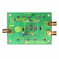
AD8330-EVALZ
Description
BOARD EVAL FOR AD8330
Manufacturer
Analog Devices Inc
Specifications of AD8330-EVALZ
Channels Per Ic
1 - Single
Amplifier Type
Variable Gain
Output Type
Differential, Rail-to-Rail
Slew Rate
1500 V/µs
-3db Bandwidth
150MHz
Operating Temperature
-40°C ~ 85°C
Current - Supply (main Ic)
20mA
Voltage - Supply, Single/dual (±)
2.7 V ~ 6 V
Board Type
Fully Populated
Utilized Ic / Part
AD8330
Silicon Manufacturer
Analog Devices
Application Sub Type
Variable Gain Amplifier
Kit Application Type
Amplifier
Silicon Core Number
AD8330
Kit Contents
Board
Lead Free Status / RoHS Status
Lead free / RoHS Compliant
Current - Output / Channel
-
Lead Free Status / RoHS Status
Lead free / RoHS Compliant, Lead free / RoHS Compliant


AD8330
PIN CONFIGURATIONS AND FUNCTION DESCRIPTIONS
Table 3. 16-Lead LFCSP Pin Function Descriptions
Pin No.
1
2
3
4
5
6
7
8
9
10
11
12
13
14
15
16
NOTES
1. THE EXPOSED PAD IS NOT CONNECTED INTERNALLY.
AND MAXIMUM THERMAL CAPABILITY, IT IS RECOMMENDED
FOR INCREASED RELIABILITY OF THE SOLDER JOINTS
THAT THE PAD BE SOLDERED TO THE GROUND PLANE.
Mnemonic
VPSI
INHI
INLO
MODE
VDBS
CMGN
COMM
VMAG
CMOP
OPLO
OPHI
VPSO
CNTR
VPOS
OFST
ENBL
EPAD
Figure 2. 16-Lead LFCSP Pin Configuration
MODE
INLO
VPSI
INHI
1
2
3
4
Description
Positive Supply for Input Stages.
Differential Signal Input, Positive
Polarity.
Differential Signal Input, Negative
Polarity.
Logic Input: Selects Gain Slope.
High = gain up vs. V
Input for Linear-in-dB Gain Control
Voltage, V
Common Baseline for Gain Control
Interfaces.
Ground for Input and Gain Control Bias
Circuitry.
Input for Gain/Amplitude Control, V
Ground for Output Stages.
Differential Signal Output, Negative
Polarity.
Differential Signal Output, Positive
Polarity.
Positive Supply for Output Stages.
Common-Mode Output Voltage Control.
Positive Supply for Inner Stages.
Used in Offset Control Modes.
Power Enable, Active High.
Exposed Pad. It is recommended that
the pad be soldered to the ground
plane.
(Not to Scale)
AD8330
TOP VIEW
PIN 1
INDICATOR
DBS
.
12 VPSO
11 OPHI
10 OPLO
9 CMOP
DBS
.
MAG
Rev. E | Page 6 of 32
.
Table 4. 16-Lead QSOP Pin Function Descriptions
Pin No.
1
2
3
4
5
6
7
8
9
10
11
12
13
14
15
16
Mnemonic
OFST
ENBL
VPSI
INHI
INLO
MODE
VDBS
CMGN
COMM
VMAG
CMOP
OPLO
OPHI
VPSO
CNTR
VPOS
Figure 3. 16-Lead QSOP Pin Configuration
M
C
O
E
V
N I
M
V
O
D
N
N I
F
P
G
S
B
L
D
B
I S
I H
O
N
T
L
E
S
Description
Used in Offset Control Modes.
Power Enable, Active High.
Positive Supply for Input Stages.
Differential Signal Input, Positive
Polarity.
Differential Signal Input, Negative
Polarity.
Logic Input: Selects Gain Slope.
High = gain up vs. V
Input for linear-in-dB Gain Control
Voltage, V
Common Baseline for Gain Control
Interfaces.
Ground for Input and Gain Control Bias
Circuitry.
Input for Gain/Amplitude Control, V
Ground for Output Stages.
Differential Signal Output, Negative
Polarity.
Differential Signal Output, Positive
Polarity.
Positive Supply for Output Stages.
Common-Mode Output Voltage Control.
Positive Supply for Inner Stages.
1
2
3
4
5
6
7
8
(Not to Scale)
AD8330
TOP VIEW
DBS
.
16
15
14
13
12
11
10
9
V
C
V
O
O
C
V
C
P
P
M
N
P
P
M
O
O
S
T
I H
L
O
A
M
R
O
O
S
G
DBS
P
M
.
MAG
.
Related parts for AD8330-EVALZ
Image
Part Number
Description
Manufacturer
Datasheet
Request
R

Part Number:
Description:
BOARD EVAL FOR AD8330
Manufacturer:
Analog Devices Inc
Datasheet:

Part Number:
Description:
±1.7g Dual-Axis IMEMS Accelerometer Evaluation Board
Manufacturer:
Analog Devices Inc
Datasheet:

Part Number:
Description:
Inertial Sensor Evaluation System
Manufacturer:
Analog Devices Inc
Datasheet:
Part Number:
Description:
Manufacturer:
Analog Devices Inc
Datasheet:
Part Number:
Description:
Manufacturer:
Analog Devices Inc
Datasheet:
Part Number:
Description:
Manufacturer:
Analog Devices Inc
Datasheet:
Part Number:
Description:
Manufacturer:
Analog Devices Inc
Datasheet:
Part Number:
Description:
Manufacturer:
Analog Devices Inc
Datasheet:
Part Number:
Description:
Manufacturer:
Analog Devices Inc
Datasheet:
Part Number:
Description:
Manufacturer:
Analog Devices Inc
Datasheet:
Part Number:
Description:
Manufacturer:
Analog Devices Inc
Datasheet:
Part Number:
Description:
Manufacturer:
Analog Devices Inc
Datasheet:
Part Number:
Description:
Manufacturer:
Analog Devices Inc
Datasheet: