AD8260-EVALZ Analog Devices Inc, AD8260-EVALZ Datasheet - Page 23
AD8260-EVALZ
Manufacturer Part Number
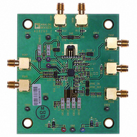
AD8260-EVALZ
Description
BOARD EVAL FOR AD8260
Manufacturer
Analog Devices Inc
Specifications of AD8260-EVALZ
Channels Per Ic
1 - Single
Amplifier Type
Variable Gain
Output Type
Differential
Slew Rate
730 V/µs
-3db Bandwidth
195MHz
Current - Output / Channel
310mA
Operating Temperature
-40°C ~ 105°C
Current - Supply (main Ic)
28.3mA
Voltage - Supply, Single/dual (±)
3.3 V ~ 10 V, ±3.3 V ~ 5 V
Board Type
Fully Populated
Utilized Ic / Part
AD8260
Silicon Manufacturer
Analog Devices
Application Sub Type
Programmable Gain Amplifier
Kit Application Type
Amplifier
Silicon Core Number
AD8260
Kit Contents
Board
Lead Free Status / RoHS Status
Lead free / RoHS Compliant
Lead Free Status / RoHS Status
Lead free / RoHS Compliant, Lead free / RoHS Compliant


Assuming R
noise simplifies to
Taking this result and dividing by 16 gives the total input-referred
noise with a short-circuited input as 2.4 nV/√Hz. When the
preamplifier is used in the inverting configuration with the
same R
does not change; however, because the gain decreases by 6 dB,
the input-referred noise increases by a factor of 2 to about
4.8 nV/√Hz. The reason for this is that the noise gain to the DGA
output of all the noise generators stays the same, but the preamp
inverting gain is ( −1×) compared to the (+2×) in the noninverting
configuration. This doubles the input-referred noise.
DGA
Referring to Figure 64, the signal path consists of a 30 dB
programmable attenuator followed by a fixed gain amplifier of
18 dB for a total DGA gain range of −12 dB to +18 dB. With the
preamplifier configured for a gain of 6 dB, the composite gain
range is −6 dB to +24 dB from single-ended preamplifier input
to differential DGA output.
The DGA plus preamplifier with 6 dB of gain implements the
following gain law:
where:
ICPT is the nominal intercept, −9 dB.
Code values are decimal from 1 to 11.
The ICPT increases as the gain of the preamplifier is increased.
For example, if the gain of the preamplifier is increased by 6 dB,
then ICPT increases to −3 dB.
GAIN CONTROL
To change the gain, the desired four bits are programmed on
Pin GNS0 to Pin GNS3, where GNS0 is the LSB (D0) and GNS3
is the MSB (D3). The states of Decimal 0 and Decimal 12 through
Decimal 15 disable the preamplifier (PrA) and DGA (see Table 4).
Gain
e
n
−out
FB1
= R
(
dB
=
S
39
= 0, R
FB2
)
1 (
=
nV
= 100 Ω as in the previous example, then e
6 .
. 3
×
/
FB1
01
16
Hz
= R
)
Code
2
dB
+
FB2
2
×
= 100 Ω, A
. 1 (
Code
29
×
) 8
+
2
ICPT
+
t
= 16, and A
. 3 (
12
(
dB
×
)
) 8
2
=
VGA
= 8, the
n-out
Rev. A | Page 23 of 32
(2)
Table 4. Gain Control Logic Table
D3
0
0
0
0
0
0
0
0
1
1
1
1
1
1
1
1
OUTPUT STAGE
The gain of the voltage feedback output stage is fixed at 18 dB and
inaccessible to the user. Otherwise, it is similar to the preamplifier
in speed and bandwidth. The overall −3 dB bandwidth of the
preamplifier and DGA combination is 230 MHz.
ATTENUATOR
The input resistance of the VGA attenuator is nominally 265 Ω.
Assuming that the default preamplifier feedback network of R
and R
The attenuator is composed of ten 3.01 dB sections for a total
attenuation span of −30.10 dB. Following the attenuator is a
fixed gain amplifier with 18 dB (8×) gain. Because of this relatively
low gain, the output offset is less than 20 mV over the operating
temperature range; the offset is largest at maximum gain because
the preamplifier offset is amplified. The VMDO pin defines the
common-mode reference for the input and output. The voltage
at VMID is half the supply voltage for single-supply operation
and 0 V when dual supplies are used.
D2
0
0
0
0
1
1
1
1
0
0
0
0
1
1
1
1
FB2
is 200 Ω, the effective preamplifier load is about 114 Ω.
D1
0
0
1
1
0
0
1
1
0
0
1
1
0
0
1
1
D0
0
1
0
1
0
1
0
1
0
1
0
1
0
1
0
1
Function
Disable
−6
−3
0
3
6
9
12
15
18
21
24
Disable
Disable
Disable
Disable
Comments
PrA and DGA powered down
The numbers in the function
column are composite gain
values in dB for the correspond-
ing code, when the preamplifier
gain is 6 dB. For other values of
preamplifier gain, the gain is
amended accordingly; for
example, if the preamplifier
gain is 12 dB, the gain values
increase by 6 dB. When using
the DGA single ended, the
composite gain decreases
by 6 dB.
PrA and DGA powered down
PrA and DGA powered down
PrA and DGA powered down
PrA and DGA powered down
AD8260
FB1
Related parts for AD8260-EVALZ
Image
Part Number
Description
Manufacturer
Datasheet
Request
R

Part Number:
Description:
High Speed, Low Power Dual Operational Amplifier
Manufacturer:
Analog Devices
Datasheet:

Part Number:
Description:
±1.7g Dual-Axis IMEMS Accelerometer Evaluation Board
Manufacturer:
Analog Devices Inc
Datasheet:

Part Number:
Description:
Inertial Sensor Evaluation System
Manufacturer:
Analog Devices Inc
Datasheet:
Part Number:
Description:
Manufacturer:
Analog Devices Inc
Datasheet:
Part Number:
Description:
Manufacturer:
Analog Devices Inc
Datasheet:
Part Number:
Description:
Manufacturer:
Analog Devices Inc
Datasheet:
Part Number:
Description:
Manufacturer:
Analog Devices Inc
Datasheet:
Part Number:
Description:
Manufacturer:
Analog Devices Inc
Datasheet:
Part Number:
Description:
Manufacturer:
Analog Devices Inc
Datasheet:
Part Number:
Description:
Manufacturer:
Analog Devices Inc
Datasheet:
Part Number:
Description:
Manufacturer:
Analog Devices Inc
Datasheet:
Part Number:
Description:
Manufacturer:
Analog Devices Inc
Datasheet:
Part Number:
Description:
Manufacturer:
Analog Devices Inc
Datasheet: