MCP6SX2DM-PCTLPD Microchip Technology, MCP6SX2DM-PCTLPD Datasheet - Page 13
MCP6SX2DM-PCTLPD
Manufacturer Part Number
MCP6SX2DM-PCTLPD
Description
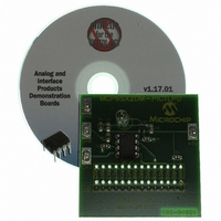
BOARD DAUGHTER PICTAIL MCP6SX2
Manufacturer
Microchip Technology
Series
PICtail™r
Datasheets
1.AC164120.pdf
(36 pages)
2.MCP6SX2DM-PCTLPD.pdf
(28 pages)
3.MCP6SX2DM-PCTLPD.pdf
(12 pages)
Specifications of MCP6SX2DM-PCTLPD
Sensor Type
Light, Current Output
Interface
Analog
Sensitivity
850nm
Voltage - Supply
2.5 V ~ 5.5 V
Embedded
No
Utilized Ic / Part
MCP6001, MCP6S22, MCP6S92
Processor To Be Evaluated
MCP6Sx2
Lead Free Status / RoHS Status
Lead free / RoHS Compliant
Sensing Range
-
Lead Free Status / Rohs Status
Lead free / RoHS Compliant
Other names
MCP6SX2DM-PCTLPDR
MCP6SX2DM-PCTLPDR
MCP6SX2DM-PCTLPDR
Available stocks
Company
Part Number
Manufacturer
Quantity
Price
Company:

Part Number:
MCP6SX2DM-PCTLPD
Manufacturer:
MICROCHIP
Quantity:
12 000


2004 Microchip Technology Inc.
1.4.1
The Personal Computer (PC) shown in Figure 1-2 needs to run on Windows
later. It provides a convenient interface for the user, communicates with the other
boards and provides power through the USB connection.
1.4.2
The PICkit™ 1 Signal Analysis PC Program configures and programs the PIC16F684
PICmicro
USB port on the PICkit 1 Flash Starter Kit. It also imports data through the same
connection and displays the data in strip chart, histogram, FFT plot and oscilloscope
plot formats. Data can be output in CSV format for importing into a spreadsheet
program.
1.4.3
The PICkit 1 Flash Starter Kit (DV164101) programs PICmicro
the PIC16C745’s USB port to communicate with the PICkit 1 Signal Analysis PC
Program. It connects to the Signal Analysis PICtail Daughter Board via a header (see
Figure 2-1).
This board provides a single +5V supply voltage for the daughter boards. It can drive
up to 5 µF on the supply; a larger capacitance may interfere with program timing.
1.4.4
This software resides on the PICkit 1 Flash Starter Kit’s PIC16C745 microcontroller.
Use version 2.0.2 or later.
1.4.5
This board is Microchip Development Tool AC164120. It connects to the PICkit 1 Flash
Starter Kit, which it uses for power and a communications link to the PC. The on-board
PIC16F684 has a 10-bit ADC that converts the Photodiode PGA PICtail™ Daughter
Board’s output voltage. The results are temporarily stored on the board’s 25LC640
serial EEPROM chips.
The +5V single supply voltage from the PICkit 1 Flash Starter Kit board is bypassed
with a bulk 1 µF capacitor and local 0.1 µF capacitors for each IC.
1.4.6
PICA2Dlab.hex is the standard file that supports the PICkit™ 1 Signal Analysis PC
Program. The PGA and 10-bit ADC configuration are selected in the Signal Analysis
PC Program and written to the PIC16F684. The PIC16F684 then sends the
command(s) over the SPI bus to the PGA.
1.4.7
A more detailed look at how the Photodiode PGA PICtail™ Daughter Board interfaces
with the other boards is shown in Figure 1-3.
®
PC Platform
PICkit™ 1 Signal Analysis PC Program
PICkit 1 Flash Starter Kit
PICkit 1 Firmware
Signal Analysis PICtail Daughter Board
Firmware for the Signal Analysis PICtail Daughter Board
Interface Details
microcontroller on the Signal Analysis PICtail Daughter Board through the
®
microcontrollers, using
Overview
DS51514A-page 9
®
98 SE or
Related parts for MCP6SX2DM-PCTLPD
Image
Part Number
Description
Manufacturer
Datasheet
Request
R

Part Number:
Description:
BOARD DEMO PICTAIL THERM MCP6SX2
Manufacturer:
Microchip Technology
Datasheet:

Part Number:
Description:
Manufacturer:
Microchip Technology Inc.
Datasheet:
Part Number:
Description:
Manufacturer:
Microchip Technology Inc.
Datasheet:
Part Number:
Description:
Manufacturer:
Microchip Technology Inc.
Datasheet:
Part Number:
Description:
Manufacturer:
Microchip Technology Inc.
Datasheet:
Part Number:
Description:
Manufacturer:
Microchip Technology Inc.
Datasheet:
Part Number:
Description:
Manufacturer:
Microchip Technology Inc.
Datasheet:
Part Number:
Description:
Manufacturer:
Microchip Technology Inc.
Datasheet:
Part Number:
Description:
Manufacturer:
Microchip Technology Inc.
Datasheet: