MCP6SX2DM-PCTLPD Microchip Technology, MCP6SX2DM-PCTLPD Datasheet - Page 21
MCP6SX2DM-PCTLPD
Manufacturer Part Number
MCP6SX2DM-PCTLPD
Description
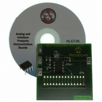
BOARD DAUGHTER PICTAIL MCP6SX2
Manufacturer
Microchip Technology
Series
PICtail™r
Datasheets
1.AC164120.pdf
(36 pages)
2.MCP6SX2DM-PCTLPD.pdf
(28 pages)
3.MCP6SX2DM-PCTLPD.pdf
(12 pages)
Specifications of MCP6SX2DM-PCTLPD
Sensor Type
Light, Current Output
Interface
Analog
Sensitivity
850nm
Voltage - Supply
2.5 V ~ 5.5 V
Embedded
No
Utilized Ic / Part
MCP6001, MCP6S22, MCP6S92
Processor To Be Evaluated
MCP6Sx2
Lead Free Status / RoHS Status
Lead free / RoHS Compliant
Sensing Range
-
Lead Free Status / Rohs Status
Lead free / RoHS Compliant
Other names
MCP6SX2DM-PCTLPDR
MCP6SX2DM-PCTLPDR
MCP6SX2DM-PCTLPDR
Available stocks
Company
Part Number
Manufacturer
Quantity
Price
Company:

Part Number:
MCP6SX2DM-PCTLPD
Manufacturer:
MICROCHIP
Quantity:
12 000


A.1
A.2
2004 Microchip Technology Inc.
INTRODUCTION
DEMONSTRATION BOARD DESCRIPTION
This appendix contains the schematics and layouts for the Photodiode PGA PICtail™
Daughter Board.
The MCP6SX2-PICTLPD Demonstration Board is constructed using a two-layer
Printed Circuit Board (PCB). The top layer is for components and traces. The bottom
layer is the ground plane.
Information on this board includes:
• Board Schematic
• Board - Top Silk-Screen And Metal Layers
• Board - Top Metal Layer
• Board - Bottom Metal Layer
A simplified schematic is shown in Figure 1.3, with the complete schematic being pre-
sented in A.4 “Board Schematic”. D
Op amp U
ance amplifier. Capacitor C
R
as an anti-aliasing filter for the ADC. The voltage V
The MCP6SX2 Programmable Gain Amplifier (PGA) can be either the MCP6S22 or the
MCP6S92. The PGA gains V
provides the capability to send another input to the ADC. It receives commands from
the PIC16F684 via the SPI™ serial bus.
The PIC16F684 is on the Signal Analysis PICtail Daughter Board (PIC16F684) and
provides an internal 10-bit ADC for measuring V
SPI serial interface.
The firmware on the PIC16F684 works with the PICkit 1 Signal Analysis PC program
(see Section 1.4.6 “Firmware for the Signal Analysis PICtail Daughter Board”).
This is a two-layer board. It has a solid ground plane on the bottom layer to minimize
EMC issues, and routes the traces in the top layer. The complete schematic is in
Sections A.4 “Board Schematic”; the board layer plots in A.5 “Board - Top
Silk-Screen And Metal Layers”, A.6 “Board - Top Metal Layer”, A.7 “Board - Bot-
tom Metal Layer” and Appendix B. Bill-Of-Materials (BOM). The Gerber files for this
board are available on the Microchip web site (www.microchip.com) and are contained
in the zip file 00951.zip.
Appendix A. Schematic and Layouts
2
and C
2
1
filter the transimpedance amplifier’s output to reduce noise. They also act
and resistor R
DAUGHTER BOARD USER’S GUIDE
1
1
PHOTODIODE PGA PICTAIL™
convert the current into a voltage; they form a transimped-
stabilizes the transimpedance amplifier.
OUT
up to produce the ADC’s input voltage V
1
is the photodiode that converts light into current.
OUT
OUT
. It also controls the PGA via the
appears at this filter’s output.
DS51514A-page 17
PGA
. It also
Related parts for MCP6SX2DM-PCTLPD
Image
Part Number
Description
Manufacturer
Datasheet
Request
R

Part Number:
Description:
BOARD DEMO PICTAIL THERM MCP6SX2
Manufacturer:
Microchip Technology
Datasheet:

Part Number:
Description:
Manufacturer:
Microchip Technology Inc.
Datasheet:
Part Number:
Description:
Manufacturer:
Microchip Technology Inc.
Datasheet:
Part Number:
Description:
Manufacturer:
Microchip Technology Inc.
Datasheet:
Part Number:
Description:
Manufacturer:
Microchip Technology Inc.
Datasheet:
Part Number:
Description:
Manufacturer:
Microchip Technology Inc.
Datasheet:
Part Number:
Description:
Manufacturer:
Microchip Technology Inc.
Datasheet:
Part Number:
Description:
Manufacturer:
Microchip Technology Inc.
Datasheet:
Part Number:
Description:
Manufacturer:
Microchip Technology Inc.
Datasheet: