DK-35TS-LPC2478 Future Designs Inc, DK-35TS-LPC2478 Datasheet - Page 32
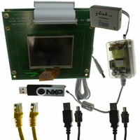
DK-35TS-LPC2478
Manufacturer Part Number
DK-35TS-LPC2478
Description
PROGRAMMERS, DEVELOPMENT SYSTEMS
Manufacturer
Future Designs Inc
Specifications of DK-35TS-LPC2478
Sensor Type
Touch Screen
Interface
I²C
Voltage - Supply
5V
Embedded
Yes, MCU, 16/32-Bit
Utilized Ic / Part
LPC2478 ARM7
For Use With
568-4742 - MODULE DIMM LPC2478 ARM7
Lead Free Status / RoHS Status
Lead free / RoHS Compliant
Sensitivity
-
Sensing Range
-
Other names
622-1034
ARM-35TS-LPC2478
ARM-35TS-LPC2478


NXP Semiconductors
LPC2478
Product data sheet
7.8.1 Features
7.8 General purpose DMA controller
Note: Synchronous static memory devices (synchronous burst mode) are not supported.
The GPDMA is an AMBA AHB compliant peripheral allowing selected LPC2478
peripherals to have DMA support.
The GPDMA enables peripheral-to-memory, memory-to-peripheral,
peripheral-to-peripheral, and memory-to-memory transactions. Each DMA stream
provides unidirectional serial DMA transfers for a single source and destination. For
example, a bidirectional port requires one stream for transmit and one for receive. The
source and destination areas can each be either a memory region or a peripheral, and
can be accessed through the AHB master.
•
•
•
•
•
•
•
•
•
•
•
•
– Asynchronous page mode read
– Programmable Wait States
– Bus turnaround delay
– Output enable and write enable delays
– Extended wait
Four chip selects for synchronous memory and four chip selects for static memory
devices.
Power-saving modes dynamically control CKE and CLKOUT to SDRAMs.
Dynamic memory self-refresh mode controlled by software.
Controller supports 2048 (A0 to A10), 4096 (A0 to A11), and 8192 (A0 to A12) row
address synchronous memory parts. That is typical 512 MB, 256 MB, and 128 MB
parts, with 4, 8, 16, or 32 data bits per device.
Separate reset domains allow auto-refresh through a chip reset if desired.
Two DMA channels. Each channel can support a unidirectional transfer.
The GPDMA can transfer data between the 16 kB SRAM, external memory, and
peripherals such as the SD/MMC, two SSPs, and the I
Single DMA and burst DMA request signals. Each peripheral connected to the
GPDMA can assert either a burst DMA request or a single DMA request. The DMA
burst size is set by programming the GPDMA.
Memory-to-memory, memory-to-peripheral, peripheral-to-memory, and
peripheral-to-peripheral transfers.
Scatter or gather DMA is supported through the use of linked lists. This means that
the source and destination areas do not have to occupy contiguous areas of memory.
Hardware DMA channel priority. Each DMA channel has a specific hardware priority.
DMA channel 0 has the highest priority and channel 1 has the lowest priority. If
requests from two channels become active at the same time, the channel with the
highest priority is serviced first.
AHB slave DMA programming interface. The GPDMA is programmed by writing to the
DMA control registers over the AHB slave interface.
All information provided in this document is subject to legal disclaimers.
Rev. 2 — 29 September 2010
Single-chip 16-bit/32-bit microcontroller
2
S interface.
LPC2478
© NXP B.V. 2010. All rights reserved.
32 of 91
Related parts for DK-35TS-LPC2478
Image
Part Number
Description
Manufacturer
Datasheet
Request
R

Part Number:
Description:
SOCKET ADAPTER BOARD
Manufacturer:
Future Designs Inc
Datasheet:

Part Number:
Description:
BOARD SCKT ADAPTER FOR TFBGA100
Manufacturer:
Future Designs Inc

Part Number:
Description:
BOARD SCKT ADAPTER FOR TFBGA180
Manufacturer:
Future Designs Inc

Part Number:
Description:
BOARD SCKT ADAPTER FOR TFBGA208
Manufacturer:
Future Designs Inc


Part Number:
Description:
BOARD DEMO FOR PHILIPS PCA9633
Manufacturer:
Future Designs Inc
Datasheet:

Part Number:
Description:
KIT LCD TOUCH 5.7" FOR LPC2478
Manufacturer:
Future Designs Inc

Part Number:
Description:
KIT LCD TOUCH 5.7" FOR LPC3250
Manufacturer:
Future Designs Inc

Part Number:
Description:
BOARD FOR LPC2103 48-LQFP
Manufacturer:
Future Designs Inc


Part Number:
Description:
KIT DEV IND REF DESIGN LPC1768
Manufacturer:
Future Designs Inc

Part Number:
Description:
BOARD FOR LPC9103 10-HVSON
Manufacturer:
Future Designs Inc
