DEMO9S08SG32AUTO Freescale Semiconductor, DEMO9S08SG32AUTO Datasheet - Page 14
DEMO9S08SG32AUTO
Manufacturer Part Number
DEMO9S08SG32AUTO
Description
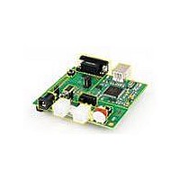
DEMO BOARD FOR MC9S08SG32
Manufacturer
Freescale Semiconductor
Type
MCUr
Specifications of DEMO9S08SG32AUTO
Contents
*
Processor To Be Evaluated
MC9S08Sx
Data Bus Width
8 bit
Interface Type
RS-232, USB
Silicon Manufacturer
Freescale
Core Architecture
HCS08
Core Sub-architecture
HCS08
Silicon Core Number
MC9S08
Silicon Family Name
S08SG
Kit Contents
Board
Rohs Compliant
Yes
For Use With/related Products
MC9S08SG32
Lead Free Status / RoHS Status
Lead free / RoHS Compliant


U S E R
Potentiometer
The DEMO9S08SH32/SG32 target board provides a 5K ohm potentiometer (POT) to simulate
analog input. The POT is decoupled to minimize noise during adjustment. Potentiometer RV1
connects to analog input PTA0. The figure below shows the USER enable position and
associated signal for the potentiometer.
Switches
The DEMO9S08SH32/SG32 provides 2 push button switches for user input. Each push button
switch provides an active low input with a pull-up resistor bias to prevent indeterminate input
conditions. Pressing a push-button switch causes a low logic input on the associated input.
The figure below shows the USER enable position and associated signal for each user switch.
LED’s
The DEMO9S08SH32/SG32 target board provides 2 green LEDs for output indication. Each
LED is an active low output. Writing a low logic level to an LED output causes the associated
LED to turn on. A series, current-limit resistor prevents excessive diode current. The figure
below shows the USER enable position and associated signal for each user LED.
User Signals
The following table shows the connections for each user I/O device.
Table 6: User I/O
User Enable
The User option header block enables or disables each User I/O device individually. User I/O
includes 4 green LEDs, 2 push button switches, one 4-position DIP switch, a Light Sensor, and
a potentiometer. Installing a shunt enables the associated option. Removing a shunt disables
the associated option. The table below shows the configuration option for each USER I/O.
G U I D E
USER
1
2
3
4
5
6
LED1
LED2
Ref Des
SW1
SW2
RV1
RZ1
PTA2/PIA/ADP2
PTA3/PIA3/ADP3
PTC0/PIC0/TPM1CH0
PTC1/PIC1/TPM1CH1
PTA0/PIA0/ACMP1+
PTA1/PIA1/ACMP1-
Signal
14
Push Button Switch
Push Button Switch
Green LED
Green LED
Potentiometer
Sensor
Device
Related parts for DEMO9S08SG32AUTO
Image
Part Number
Description
Manufacturer
Datasheet
Request
R

Part Number:
Description:
Manufacturer:
Freescale Semiconductor, Inc
Datasheet:
Part Number:
Description:
Manufacturer:
Freescale Semiconductor, Inc
Datasheet:
Part Number:
Description:
Manufacturer:
Freescale Semiconductor, Inc
Datasheet:
Part Number:
Description:
Manufacturer:
Freescale Semiconductor, Inc
Datasheet:
Part Number:
Description:
Manufacturer:
Freescale Semiconductor, Inc
Datasheet:
Part Number:
Description:
Manufacturer:
Freescale Semiconductor, Inc
Datasheet:
Part Number:
Description:
Manufacturer:
Freescale Semiconductor, Inc
Datasheet:
Part Number:
Description:
Manufacturer:
Freescale Semiconductor, Inc
Datasheet:
Part Number:
Description:
Manufacturer:
Freescale Semiconductor, Inc
Datasheet:
Part Number:
Description:
Manufacturer:
Freescale Semiconductor, Inc
Datasheet:
Part Number:
Description:
Manufacturer:
Freescale Semiconductor, Inc
Datasheet:
Part Number:
Description:
Manufacturer:
Freescale Semiconductor, Inc
Datasheet:
Part Number:
Description:
Manufacturer:
Freescale Semiconductor, Inc
Datasheet:
Part Number:
Description:
Manufacturer:
Freescale Semiconductor, Inc
Datasheet:
Part Number:
Description:
Manufacturer:
Freescale Semiconductor, Inc
Datasheet: