DEMO9S08SG32AUTO Freescale Semiconductor, DEMO9S08SG32AUTO Datasheet - Page 4
DEMO9S08SG32AUTO
Manufacturer Part Number
DEMO9S08SG32AUTO
Description
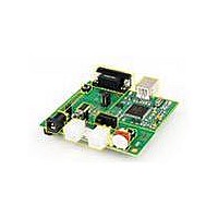
DEMO BOARD FOR MC9S08SG32
Manufacturer
Freescale Semiconductor
Type
MCUr
Specifications of DEMO9S08SG32AUTO
Contents
*
Processor To Be Evaluated
MC9S08Sx
Data Bus Width
8 bit
Interface Type
RS-232, USB
Silicon Manufacturer
Freescale
Core Architecture
HCS08
Core Sub-architecture
HCS08
Silicon Core Number
MC9S08
Silicon Family Name
S08SG
Kit Contents
Board
Rohs Compliant
Yes
For Use With/related Products
MC9S08SG32
Lead Free Status / RoHS Status
Lead free / RoHS Compliant


U S E R
CAUTIONARY NOTES
1) Electrostatic Discharge (ESD) prevention measures should be used when handling this
2) Axiom Manufacturing does not assume any liability arising out of the application or use of
3) 3) EMC Information on the DEMO9S08SH32/SG32 board:
TERMINOLOGY
This development module utilizes option select jumpers to configure default board operation.
Terminology for application of the option jumpers is as follows:
product. ESD damage is not a warranty repair item.
any product or circuit described herein; neither does it convey any license under patent
rights or the rights of others.
a) This product as shipped from the factory with associated power supplies and cables,
b) This product is designed and intended for use as a development platform for hardware
c) In a domestic environment, this product may cause radio interference in which case the
d) Attaching additional wiring to this product or modifying the products operation from the
Jumper – a plastic shunt that connects 2 terminals electrically
Jumper on, in, or installed = jumper is a plastic shunt that fits across 2 pins and the shunt is
installed so that the 2 pins are connected with the shunt.
Jumper off, out, or idle = jumper or shunt is installed so that only 1 pin holds the shunt, no 2
pins are connected, or jumper is removed. It is recommended that the jumpers be placed
idle by installing on 1 pin so they will not be lost.
Cut-Trace – a circuit trace connection between component pads. The circuit trace may be
cut using a knife to break the default connection. To reconnect the circuit, simply install a
suitably sized 0-ohm resistor or attach a wire across the pads.
Signal names followed by an asterisk (*) denote active-low signals.
has been verified to meet with requirements of CE and the FCC as a CLASS A product.
or software in an educational or professional laboratory.
user may be required to take adequate prevention measures.
factory default as shipped may effect its performance and cause interference with
nearby electronic equipment.
measures should be taken.
G U I D E
If such interference is detected, suitable mitigating
4
Related parts for DEMO9S08SG32AUTO
Image
Part Number
Description
Manufacturer
Datasheet
Request
R

Part Number:
Description:
Manufacturer:
Freescale Semiconductor, Inc
Datasheet:
Part Number:
Description:
Manufacturer:
Freescale Semiconductor, Inc
Datasheet:
Part Number:
Description:
Manufacturer:
Freescale Semiconductor, Inc
Datasheet:
Part Number:
Description:
Manufacturer:
Freescale Semiconductor, Inc
Datasheet:
Part Number:
Description:
Manufacturer:
Freescale Semiconductor, Inc
Datasheet:
Part Number:
Description:
Manufacturer:
Freescale Semiconductor, Inc
Datasheet:
Part Number:
Description:
Manufacturer:
Freescale Semiconductor, Inc
Datasheet:
Part Number:
Description:
Manufacturer:
Freescale Semiconductor, Inc
Datasheet:
Part Number:
Description:
Manufacturer:
Freescale Semiconductor, Inc
Datasheet:
Part Number:
Description:
Manufacturer:
Freescale Semiconductor, Inc
Datasheet:
Part Number:
Description:
Manufacturer:
Freescale Semiconductor, Inc
Datasheet:
Part Number:
Description:
Manufacturer:
Freescale Semiconductor, Inc
Datasheet:
Part Number:
Description:
Manufacturer:
Freescale Semiconductor, Inc
Datasheet:
Part Number:
Description:
Manufacturer:
Freescale Semiconductor, Inc
Datasheet:
Part Number:
Description:
Manufacturer:
Freescale Semiconductor, Inc
Datasheet: