TOOLSTICK542PP Silicon Laboratories Inc, TOOLSTICK542PP Datasheet - Page 151
TOOLSTICK542PP
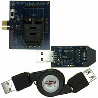
Manufacturer Part Number
TOOLSTICK542PP
Description
PLATFORM PROG TOOLSTICK F542
Manufacturer
Silicon Laboratories Inc
Series
ToolStickr
Type
Microcontroller Programmerr
Specifications of TOOLSTICK542PP
Contents
2 Boards and USB Connecting Cable
Processor To Be Evaluated
C8051F542
Interface Type
USB
Operating Supply Voltage
2.7 V to 3.6 V
Lead Free Status / RoHS Status
Lead free / RoHS Compliant
For Use With/related Products
C8051F542
Lead Free Status / Rohs Status
Lead free / RoHS Compliant
Other names
336-1718


Registers XBR0, XBR1, and XBR2 are used to assign the digital I/O resources to the physical I/O Port
pins. Note that when the SMBus is selected, the Crossbar assigns both pins associated with the SMBus
(SDA and SCL); and similarly when the UART or LIN are selected, the Crossbar assigns both pins associ-
ated with the peripheral (TX and RX). UART0 pin assignments are fixed for bootloading purposes: UART
TX0 is always assigned to P0.4; UART RX0 is always assigned to P0.5. Standard Port I/Os appear contig-
uously after the prioritized functions have been assigned.
Important Note: The SPI can be operated in either 3-wire or 4-wire modes, pending the state of the
NSSMD1–NSSMD0 bits in register SPI0CN. According to the SPI mode, the NSS signal may or may not
be routed to a Port pin.
As an example configuration, if SPI0 in 4-wire mode, and PCA0 Modules 0, 1, and 2 are enabled on the
crossbar with P0.1, P0.2, and P0.5 skipped, the registers should be set as follows: XBR0 = 0x04 (SPI0
enabled), XBR1 = 0x0C (PCA0 modules 0, 1, and 2 enabled), XBR2 = 0x40 (Crossbar enabled), and
P0SKIP = 0x26 (P0.1, P0.2, and P0.5 skipped). The resulting crossbar would look as shown in
Figure 18.4.
Port
Special
Function
Signals
PIN I/O
UART_TX
UART_RX
SCK
MISO
MOSI
NSS
SDA
SCL
CP0
CP0A
CP1
CP1A
SYSCLK
CEX0
CEX1
CEX2
CEX3
CEX4
CEX5
ECI
T0
T1
LIN_TX
LIN_RX
0 1 2 3
Figure 18.3. Peripheral Availability on Port I/O Pins
P0
4 5 6
7 0 1 2
Rev. 1.1
3 4 5 6
P1
7 0 1 2
available on the 32-pin
P2.2-P2.7, P3.0 only
3 4 5 6
P2
packages
C8051F54x
7 0
P3
151
Related parts for TOOLSTICK542PP
Image
Part Number
Description
Manufacturer
Datasheet
Request
R

Part Number:
Description:
KIT TOOL EVAL SYS IN A USB STICK
Manufacturer:
Silicon Laboratories Inc
Datasheet:

Part Number:
Description:
TOOLSTICK DEBUG ADAPTER
Manufacturer:
Silicon Laboratories Inc
Datasheet:

Part Number:
Description:
TOOLSTICK BASE ADAPTER
Manufacturer:
Silicon Laboratories Inc
Datasheet:

Part Number:
Description:
TOOLSTICK DAUGHTER CARD
Manufacturer:
Silicon Laboratories Inc
Datasheet:

Part Number:
Description:
TOOLSTICK DAUGHTER CARD
Manufacturer:
Silicon Laboratories Inc
Datasheet:

Part Number:
Description:
TOOLSTICK DAUGHTER CARD
Manufacturer:
Silicon Laboratories Inc
Datasheet:

Part Number:
Description:
TOOLSTICK DAUGHTER CARD
Manufacturer:
Silicon Laboratories Inc
Datasheet:

Part Number:
Description:
KIT STARTER TOOLSTICK
Manufacturer:
Silicon Laboratories Inc
Datasheet:

Part Number:
Description:
KIT UNIVERSITY TOOLSTICK STARTER
Manufacturer:
Silicon Laboratories Inc
Datasheet:

Part Number:
Description:
DAUGHTER CARD TOOLSTICK F330
Manufacturer:
Silicon Laboratories Inc
Datasheet:

Part Number:
Description:
CARD DAUGHTER UNIVRSTY TOOLSTICK
Manufacturer:
Silicon Laboratories Inc
Datasheet:

Part Number:
Description:
DAUGHTER CARD TOOLSTICK F582
Manufacturer:
Silicon Laboratories Inc
Datasheet:

Part Number:
Description:
DAUGHTER CARD TOOLSTICK F500
Manufacturer:
Silicon Laboratories Inc
Datasheet:

Part Number:
Description:
DAUGHTER CARD TOOLSTICK F540
Manufacturer:
Silicon Laboratories Inc
Datasheet:

Part Number:
Description:
DAUGHTER CARD TOOLSTICK F560
Manufacturer:
Silicon Laboratories Inc
Datasheet: