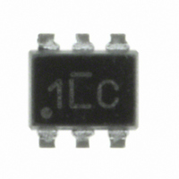
AOZ8204KI Alpha & Omega Semiconductor Inc, AOZ8204KI Datasheet - Page 4

AOZ8204KI
Manufacturer Part Number
AOZ8204KI
Description
IC TVS DIODE ARRAY 4-LINE SC89-6
Manufacturer
Alpha & Omega Semiconductor Inc
Datasheet
1.AOZ8204KI.pdf
(7 pages)
Specifications of AOZ8204KI
Voltage - Reverse Standoff (typ)
5V
Voltage - Breakdown
8V
Polarization
4 Channel Array - Unidirectional
Mounting Type
Surface Mount
Package / Case
SC-89-6, SOT-563F, SOT-666
Lead Free Status / RoHS Status
Lead free / RoHS Compliant
Power (watts)
-
Other names
785-1167-2
Available stocks
Company
Part Number
Manufacturer
Quantity
Price
Company:
Part Number:
AOZ8204KI
Manufacturer:
CERATECH
Quantity:
6 023
Applications Information
Device Connection for Protection of Four Data Lines
These devices are designed to protect up to four
unidirectional data lines. The device is connected as
follows.
1. Unidirectional protection of four I/O lines is achieved
Device Connection for Protection of Two
Bidirectional Data Lines
These devices are designed to protect up to two
bidirectional data lines. The device is connected as
follows.
1. Bidirectional protection of two I/O lines is achieved by
Circuit Board Layout Recommendations for
Suppression of ESD
Good circuit board layout is critical for the suppression of
ESD induced transients. The following guidelines are
recommended:
Rev. 1.9 June 2009
Place the TVS near the input terminals or connectors
to restrict transient coupling.
Minimize the path length between the TVS and the
protected line.
Minimize all conductive loops including power and
ground loops.
The ESD transient return path to ground should be
kept as short as possible.
Never run critical signals near board edges.
Use ground planes whenever possible.
by connecting pins 1, 3, 4, and 6 to the data lines.
Connect pin 2 to ground. The ground connection
should be made directly to the ground plane for best
results. The path length is kept as short as possible
to reduce the effects of parasitic inductance in the
board traces.
connecting pins 1 and 3 to the data lines. Connect
pin 4 and 6 to ground. The ground connection should
be made directly to the ground plane for best results.
The path length is kept as short as possible to
reduce the effects of parasitic inductance in the
board traces.
www.aosmd.com
Circuit Diagram
1
Circuit Diagram
1
3
4
2
3
4
6
6
I/O1
I/O2
Protection of Two Bidirectional Lines
I/O1
I/O2
Protection of Four Unidirectional Lines
I/O3
I/O4
1
2
3
1
2
3
6
5
4
6
5
4
AOZ8204
Page 4 of 7


