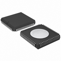
P87C554SFAA,512 NXP Semiconductors, P87C554SFAA,512 Datasheet - Page 38

P87C554SFAA,512
Manufacturer Part Number
P87C554SFAA,512
Description
IC 80C51 MCU 16K OTP 64-PLCC
Manufacturer
NXP Semiconductors
Series
87Cr
Specifications of P87C554SFAA,512
Core Processor
8051
Core Size
8-Bit
Speed
16MHz
Connectivity
EBI/EMI, I²C, UART/USART
Peripherals
POR, PWM, WDT
Number Of I /o
40
Program Memory Size
16KB (16K x 8)
Program Memory Type
OTP
Ram Size
512 x 8
Voltage - Supply (vcc/vdd)
2.7 V ~ 5.5 V
Data Converters
A/D 8x10b
Oscillator Type
Internal
Operating Temperature
-40°C ~ 85°C
Package / Case
68-PLCC
Cpu Family
87C
Device Core
80C51
Device Core Size
8b
Frequency (max)
16MHz
Interface Type
I2C/UART
Total Internal Ram Size
512Byte
# I/os (max)
40
Number Of Timers - General Purpose
3
Operating Supply Voltage (typ)
5V
Operating Supply Voltage (max)
5.5V
Operating Supply Voltage (min)
4.5V
On-chip Adc
7-chx10-bit
Instruction Set Architecture
CISC
Operating Temp Range
-40C to 85C
Operating Temperature Classification
Industrial
Mounting
Surface Mount
Pin Count
68
Package Type
PLCC
Processor Series
P87C5x
Core
80C51
Data Bus Width
8 bit
Data Ram Size
512 B
Maximum Clock Frequency
16 MHz
Number Of Programmable I/os
40
Number Of Timers
3
Operating Supply Voltage
2.7 V to 5.5 V
Maximum Operating Temperature
+ 85 C
Mounting Style
SMD/SMT
3rd Party Development Tools
PK51, CA51, A51, ULINK2
Minimum Operating Temperature
- 40 C
Package
68PLCC
Family Name
87C
Maximum Speed
16 MHz
Lead Free Status / RoHS Status
Lead free / RoHS Compliant
Eeprom Size
-
Lead Free Status / Rohs Status
Compliant
Other names
568-1255-5
935263922512
P87C554SFAA
935263922512
P87C554SFAA
Available stocks
Company
Part Number
Manufacturer
Quantity
Price
Company:
Part Number:
P87C554SFAA,512
Manufacturer:
Maxim
Quantity:
145
Company:
Part Number:
P87C554SFAA,512
Manufacturer:
NXP Semiconductors
Quantity:
10 000
Philips Semiconductors
In the following text, it is assumed that ENS1 = “1”.
STA
STA = “1”: When the STA bit is set to enter a master mode, the SIO1
hardware checks the status of the I2C bus and generates a START
condition if the bus is free. If the bus is not free, then SIO1 waits for
a STOP condition (which will free the bus) and generates a START
condition after a delay of a half clock period of the internal serial
clock generator.
If STA is set while SIO1 is already in a master mode and one or
more bytes are transmitted or received, SIO1 transmits a repeated
START condition. STA may be set at any time. STA may also be set
when SIO1 is an addressed slave.
2002 Mar 25
80C51 8-bit microcontroller – 12 clock operation
16K/512 OTP/RAM, 8 channel 10-bit A/D, I
capture/compare, high I/O
, THE
SHIFT ACK & S1DAT
(1) Valid data in S1DAT
(2) Shifting data in S1DAT and ACK
(3) High level on SDA
START F
SHIFT BSD7
S1DAT
BSD7
LAG
SDA
SCL
SDA
ACK
SCL
LOADED BY THE CPU
(1)
D7
D7
(2)
(2)
D6
D6
SHIFT PULSES
(2)
(2)
Figure 38. Serial Input/Output Configuration
Figure 39. Shift-in and Shift-out Timing
D5
D5
BSD7
(2)
(2)
2
D4
D4
C, PWM,
(2)
(2)
INTERNAL BUS
36
D3
D3
STA = “0”: When the STA bit is reset, no START condition or
repeated START condition will be generated.
STO
STO = “1”: When the STO bit is set while SIO1 is in a master mode,
a STOP condition is transmitted to the I
condition is detected on the bus, the SIO1 hardware clears the STO
flag. In a slave mode, the STO flag may be set to recover from an
error condition. In this case, no STOP condition is transmitted to the
I
condition has been received and switches to the defined “not
addressed” slave receiver mode. The STO flag is automatically
cleared by hardware.
2
S1DAT
(2)
(2)
C bus. However, the SIO1 hardware behaves as if a STOP
, THE
8
D2
D2
STOP F
(2)
(2)
D1
D1
LAG
(2)
(2)
ACK
D0
D0
(2)
(2)
(3)
A
SU00969
(1)
2
A
C bus. When the STOP
SHIFT IN
SU00970
SHIFT OUT
P87C554
Product data


