STM8L101K3T6 STMicroelectronics, STM8L101K3T6 Datasheet - Page 39
STM8L101K3T6
Manufacturer Part Number
STM8L101K3T6
Description
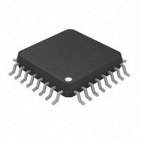
MCU 8KB FLASH MEM LP 32-LQFP
Manufacturer
STMicroelectronics
Series
STM8L EnergyLiter
Datasheet
1.STM8L101-EVAL.pdf
(81 pages)
Specifications of STM8L101K3T6
Core Processor
STM8
Core Size
8-Bit
Speed
16MHz
Connectivity
I²C, SPI, UART/USART
Peripherals
Infrared, POR, PWM, WDT
Number Of I /o
30
Program Memory Size
8KB (8K x 8)
Program Memory Type
FLASH
Eeprom Size
2K x 8
Ram Size
1.5K x 8
Voltage - Supply (vcc/vdd)
1.65 V ~ 3.6 V
Oscillator Type
Internal
Operating Temperature
-40°C ~ 85°C
Package / Case
32-LQFP
Processor Series
STM8L10x
Core
STM8
Data Bus Width
8 bit
Data Ram Size
1.5 KB
Interface Type
I2C/SPI/UART
Maximum Clock Frequency
16 MHz
Number Of Programmable I/os
30
Number Of Timers
3
Operating Supply Voltage
1.65 V to 3.6 V
Maximum Operating Temperature
+ 85 C
Mounting Style
SMD/SMT
3rd Party Development Tools
EWSTM8
Minimum Operating Temperature
- 40 C
For Use With
497-10038 - EVAL KIT LCD COUNTER STM8L101497-10039 - EVAL DEV KIT FOR STM8L101
Lead Free Status / RoHS Status
Lead free / RoHS Compliant
Data Converters
-
Lead Free Status / Rohs Status
Lead free / RoHS Compliant
Other names
497-10036
STM8L101K3T6
STM8L101K3T6
Available stocks
Company
Part Number
Manufacturer
Quantity
Price
Company:

Part Number:
STM8L101K3T6
Manufacturer:
EXAR
Quantity:
4 430
Company:
Part Number:
STM8L101K3T6
Manufacturer:
STMicroelectronics
Quantity:
10 000
Part Number:
STM8L101K3T6
Manufacturer:
ST
Quantity:
20 000


STM8L101xx
Table 14.
1. Positive injection is not possible on these I/Os. V
2. I
3. When several inputs are submitted to a current injection, the maximum I
Table 15.
Symbol
never be exceeded. A negative injection is induced by V
cannot be respected, the injection current must be limited externally to the I
injection is induced by V
positive and negative injected currents (instantaneous values). These results are based on
characterization with I
INJ(PIN)
T
Symbol
I
STG
INJ(PIN)
T
I
INJ(PIN)
I
I
J
VDD
VSS
I
IO
must never be exceeded. This is implicitly insured if V
Current characteristics
Thermal characteristics
Storage temperature range
Maximum junction temperature
Total current into V
Total current out of V
Output current sunk by IR_TIM pin (with high sink LED
driver capability)
Output current sunk by any other I/O and control pin
Output current sourced by any I/Os and control pin
Injected current on true open-drain pins (PC0 and PC1)
Injected current on any other pin
Total injected current (sum of all I/O and control pins)
INJ(PIN)
IN
>V
DD
maximum current injection on four I/O port pins of the device.
while a negative injection is induced by V
Doc ID 15275 Rev 11
Ratings
DD
SS
power line (source)
ground line (sink)
Ratings
IN
maximum must always be respected. I
(2)
IN
<V
SS
IN
.
maximum is respected. If V
INJ(PIN)
IN
<V
INJ(PIN)
(3)
SS
-65 to +150
(1)
is the absolute sum of the
.
Electrical parameters
Value
value. A positive
150
INJ(PIN)
Max.
±25
-25
±5
80
80
80
25
-5
IN
maximum
must
Unit
Unit
° C
mA
39/81
Related parts for STM8L101K3T6
Image
Part Number
Description
Manufacturer
Datasheet
Request
R

Part Number:
Description:
EVAL DEV KIT FOR STM8L101
Manufacturer:
STMicroelectronics
Datasheet:

Part Number:
Description:
8-bit ultralow power microcontroller with up to 8 Kbytes Flash multifunction timers, comparators, USART, SPI, I2C
Manufacturer:
STMICROELECTRONICS [STMicroelectronics]
Datasheet:

Part Number:
Description:
BOARD EVALUATION STM8L15X
Manufacturer:
STMicroelectronics
Datasheet:

Part Number:
Description:
IC MCU 8BIT 16KB FLASH 48LQFP
Manufacturer:
STMicroelectronics
Datasheet:

Part Number:
Description:
IC MCU 8BIT 32KB FLASH 32LQFP
Manufacturer:
STMicroelectronics
Datasheet:

Part Number:
Description:
MCU 8BIT 4K FLASH 20TSSOP
Manufacturer:
STMicroelectronics
Datasheet:
Part Number:
Description:
MCU 8BIT 8K FLASH 20TSSOP
Manufacturer:
STMicroelectronics
Datasheet:
Part Number:
Description:
IC MCU 8BIT 16KB FLASH 32LQFP
Manufacturer:
STMicroelectronics
Datasheet:
Part Number:
Description:
IC MCU 8BIT 32KB FLASH 48LQFP
Manufacturer:
STMicroelectronics
Datasheet:
Part Number:
Description:
IC MCU 8BIT 32KB FLASH 32LQFP
Manufacturer:
STMicroelectronics
Datasheet:
Part Number:
Description:
IC MCU 8BIT 16KB FLASH 48LQFP
Manufacturer:
STMicroelectronics
Datasheet:
Part Number:
Description:
IC MCU 8BIT 16KB FLASH 32LQFP
Manufacturer:
STMicroelectronics
Datasheet:
Part Number:
Description:
IC MCU 8BIT 32KB FLASH 48LQFP
Manufacturer:
STMicroelectronics
Datasheet:

Part Number:
Description:
BOARD EVALUATION FOR STM32L
Manufacturer:
STMicroelectronics
Datasheet:

Part Number:
Description:
8 BITS MICROCONTR
Manufacturer:
STMicroelectronics
Datasheet: