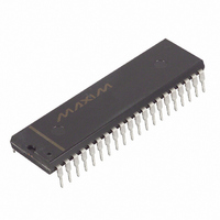
DS80C310-MCG+ Maxim Integrated Products, DS80C310-MCG+ Datasheet - Page 11

DS80C310-MCG+
Manufacturer Part Number
DS80C310-MCG+
Description
IC MCU HI SPEED 25MHZ 40-DIP
Manufacturer
Maxim Integrated Products
Series
80Cr
Datasheet
1.DS80C310FCG.pdf
(22 pages)
Specifications of DS80C310-MCG+
Core Processor
8051
Core Size
8-Bit
Speed
25MHz
Connectivity
EBI/EMI, SIO, UART/USART
Peripherals
Brown-out Detect/Reset, POR
Number Of I /o
32
Program Memory Type
ROMless
Ram Size
256 x 8
Voltage - Supply (vcc/vdd)
4.5 V ~ 5.5 V
Oscillator Type
External
Operating Temperature
0°C ~ 70°C
Package / Case
40-DIP (0.600", 15.24mm)
Processor Series
80C
Core
8051
Data Bus Width
8 bit
Program Memory Size
64 KB
Data Ram Size
64 KB
Maximum Clock Frequency
25 MHz
Number Of Programmable I/os
32
Number Of Timers
3
Operating Supply Voltage
5 V
Maximum Operating Temperature
+ 70 C
Mounting Style
Through Hole
3rd Party Development Tools
PK51, CA51, A51, ULINK2
Minimum Operating Temperature
0 C
Controller Family/series
(8051) 8052
No. Of I/o's
32
Ram Memory Size
256Byte
Cpu Speed
25MHz
No. Of Timers
3
Embedded Interface Type
UART
Digital Ic Case Style
DIP
Rohs Compliant
Yes
Interface Type
UART
Lead Free Status / RoHS Status
Lead free / RoHS Compliant
Eeprom Size
-
Program Memory Size
-
Data Converters
-
Lead Free Status / Rohs Status
Lead free / RoHS Compliant
ABSOLUTE MAXIMUM RATINGS
Voltage Range on Any Pin Relative to Ground……………………………………...-0.3V to (V
Voltage Range on V
Operating Temperature Range………………………………………………………………-40 C to +85 C
Storage Temperature Range……………………………………………………………….-55 C to +125 C
Soldering Temperature………………………………………….See IPC/JEDEC J-STD-020 Specification
This is a stress rating only and functional operation of the device at these or any other conditions above those indicated in the
operation sections of this specification is not implied. Exposure to absolute maximum rating conditions for extended periods of
time may affect device reliability.
DC ELECTRICAL CHARACTERISTICS
(V
Note 1:
Note 2:
Note 3:
Note 4:
Note 5:
Supply Voltage
Supply Current Active Mode
at 25MHz
Supply Current Idle Mode
at 25MHz
Supply Current Stop Mode
Input Low Level
Input High Level (Except XTAL1 and
RST)
Input High Level XTAL1 and RST
Output Low Voltage Ports 1, 3
at I
Output Low Voltage Port 0, 2, ALE,
Output High Voltage Port 1, 3, ALE,
Output High Voltage Ports 1, 3
at I
Output High Voltage Port 0, 2, ALE,
Input Low Current Ports 1, 3
at 0.45V
Transition Current from 1 to 0
Ports 1, 3 at 2V
Input Leakage Port 0, Bus Mode
RST Pulldown Resistance
PSEN
PSEN
PSEN
CC
OL
OH
= 4.5V to 5.5V, T
= 1.6mA
= -1.5mA
at I
at I
at I
are guaranteed by design and not product tested.
disconnected.
All parameters apply to both commercial and industrial temperature operation unless otherwise noted. Specifications to -40C
All voltages are referenced to ground.
Active current is measured with a 25MHz clock source driving XTAL1, V
Idle mode current is measured with a 25MHz clock source driving XTAL1, V
Stop mode current measured with XTAL1 and RST grounded, V
OL
OH
OH
PARAMETER
= 3.2mA
= -50A
= -8mA
CC
A
Relative to Ground………………………………………………….-0.3V to +6.0V
= -40C to +85C.) (Note 1)
SYMBOL
V
V
V
I
V
V
R
I
V
V
V
V
I
STOP
IDLE
I
I
I
CC
OH1
OH2
OH3
RST
OL1
OL2
TL
IH2
IL
CC
L
IH
IL
11 of 22
MIN
-300
-0.3
4.0
2.0
3.5
2.4
2.4
2.4
50
CC
=5.5V, all other pins disconnected.
TYP
0.15
0.15
CC
5.0
30
15
1
= RST = 5.5V, all other pins disconnected.
CC
= 5.5V, RST at ground, all other pins
MAX
V
V
+300
+0.8
0.45
0.45
-650
170
-55
5.5
0.3
0.3
CC
CC
+
+
UNITS
mA
mA
A
A
A
A
k
V
V
V
V
V
V
V
V
V
CC
NOTES
DS80C310
+ 0.5V)
2, 6
2, 7
2, 8
2, 6
10
11
2
3
4
5
2
2
2
2
9


