PIC12CE519/JW Microchip Technology, PIC12CE519/JW Datasheet - Page 285
PIC12CE519/JW
Manufacturer Part Number
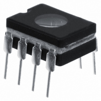
PIC12CE519/JW
Description
IC MCU EPROM 1KX12 W/EE 8CDIP
Manufacturer
Microchip Technology
Series
PIC® 12Cr
Datasheets
1.PIC16F688T-ISL.pdf
(688 pages)
2.PIC12C508A-04SM.pdf
(113 pages)
3.PIC12C508A-04SM.pdf
(4 pages)
4.PIC12CE518-04SM.pdf
(16 pages)
Specifications of PIC12CE519/JW
Core Processor
PIC
Core Size
8-Bit
Speed
4MHz
Peripherals
POR, WDT
Number Of I /o
5
Program Memory Size
1.5KB (1K x 12)
Program Memory Type
EPROM, UV
Eeprom Size
16 x 8
Ram Size
41 x 8
Voltage - Supply (vcc/vdd)
3 V ~ 5.5 V
Oscillator Type
Internal
Operating Temperature
0°C ~ 70°C
Package / Case
8-CDIP (0.300", 7.62mm) Window
For Use With
ISPICR1 - ADAPTER IN-CIRCUIT PROGRAMMINGDVA12XP080 - ADAPTER DEVICE FOR MPLAB-ICEAC124001 - MODULE SKT PROMATEII 8DIP/SOIC
Lead Free Status / RoHS Status
Contains lead / RoHS non-compliant
Data Converters
-
Connectivity
-
Available stocks
Company
Part Number
Manufacturer
Quantity
Price

Part Number:
PIC12CE519/JW
Manufacturer:
MICROCH
Quantity:
20 000


17.3
17.3.1
1997 Microchip Technology Inc.
Operation
SPI Mode
The SPI mode allows 8-bits of data to be synchronously transmitted and received simulta-
neously. All four modes of SPI are supported. To accomplish communication, typically three pins
are used:
• Serial Data Out (SDO)
• Serial Data In (SDI)
• Serial Clock (SCK)
Additionally a fourth pin may be used when in a slave mode of operation:
• Slave Select (SS)
When initializing the SPI, several options need to be specified. This is done by programming the
appropriate control bits in the SSPCON1 register (SSPCON1<5:0>) and SSPSTAT<7:6>. These
control bits allow the following to be specified:
• Master Mode (SCK is the clock output)
• Slave Mode (SCK is the clock input)
• Clock Polarity (Idle state of SCK)
• Data input sample phase (middle or end of data output time)
• Clock edge (output data on rising/falling edge of SCK)
• Clock Rate (Master mode only)
• Slave Select Mode (Slave mode only)
Figure 17-4
Figure 17-4:
shows the block diagram of the SSP module, when in SPI mode.
SSP Block Diagram (SPI Mode)
SDO
SCK
SDI
SS
Preliminary
Read
SS Control
Select
SMP:CKE
Edge
Enable
bit0
Select
Edge
SSPBUF reg
TRIS bit
Data to TX/RX in SSPSR
2
SSPM3:SSPM0
SSPSR reg
Clock Select
Section 17. MSSP
4
2
Write
Prescaler
4, 16, 64
clock
shift
TMR2 output
data bus
Internal
2
T
OSC
DS31017A-page 17-9
17
Related parts for PIC12CE519/JW
Image
Part Number
Description
Manufacturer
Datasheet
Request
R

Part Number:
Description:
8-Pin/ 8-Bit CMOS Microcontroller with EEPROM Data Memory
Manufacturer:
Microchip Technology
Part Number:
Description:
IC, 8BIT MCU, PIC12, 32MHZ, DFN-8
Manufacturer:
Microchip Technology
Datasheet:
Part Number:
Description:
IC, 8BIT MCU, PIC12, 32MHZ, DFN-8
Manufacturer:
Microchip Technology
Datasheet:

Part Number:
Description:
Manufacturer:
Microchip Technology Inc.
Datasheet:
Part Number:
Description:
Manufacturer:
Microchip Technology Inc.
Datasheet:
Part Number:
Description:
Manufacturer:
Microchip Technology Inc.
Datasheet:
Part Number:
Description:
Manufacturer:
Microchip Technology Inc.
Datasheet:
Part Number:
Description:
Manufacturer:
Microchip Technology Inc.
Datasheet:
Part Number:
Description:
Manufacturer:
Microchip Technology Inc.
Datasheet:
Part Number:
Description:
Manufacturer:
Microchip Technology Inc.
Datasheet: