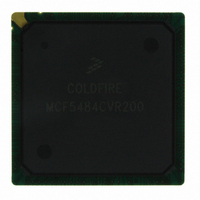
MCF5484CVR200 Freescale Semiconductor, MCF5484CVR200 Datasheet - Page 8

MCF5484CVR200
Manufacturer Part Number
MCF5484CVR200
Description
IC MPU 32BIT COLDF 388-PBGA
Manufacturer
Freescale Semiconductor
Series
MCF548xr
Datasheet
1.MCF5480CVR166.pdf
(34 pages)
Specifications of MCF5484CVR200
Core Processor
Coldfire V4E
Core Size
32-Bit
Speed
200MHz
Connectivity
CAN, EBI/EMI, Ethernet, I²C, SPI, UART/USART, USB
Peripherals
DMA, PWM, WDT
Number Of I /o
99
Program Memory Type
ROMless
Ram Size
32K x 8
Voltage - Supply (vcc/vdd)
1.43 V ~ 1.58 V
Oscillator Type
External
Operating Temperature
-40°C ~ 85°C
Package / Case
388-BGA
Processor Series
MCF548x
Core
ColdFire V4
Data Bus Width
32 bit
Data Ram Size
32 KB
Maximum Clock Frequency
83 MHz
Operating Supply Voltage
3 V to 3.6 V
Maximum Operating Temperature
+ 85 C
3rd Party Development Tools
JLINK-CF-BDM26, EWCF
Development Tools By Supplier
M5485EVBE, M5485EVBGHSE, M5484LITEKITE
Minimum Operating Temperature
- 40 C
Program Memory Size
64KB
Cpu Speed
200MHz
Embedded Interface Type
I2C, UART, DMA
Digital Ic Case Style
BGA
No. Of Pins
388
Rohs Compliant
Yes
Family Name
MCF5xxx
Device Core
ColdFire V4e
Device Core Size
32b
Frequency (max)
200MHz
Instruction Set Architecture
RISC
Supply Voltage 1 (typ)
1.5/3.3V
Operating Supply Voltage (max)
1.58/3.6V
Operating Supply Voltage (min)
1.43/3V
Operating Temp Range
-40C to 85C
Operating Temperature Classification
Industrial
Mounting
Surface Mount
Pin Count
388
Package Type
BGA
For Use With
M5485EVBGHSE - KIT DEV GHS FOR M5485EVBM5485EVBGHS - KIT DEV GHS FOR M5485EVBM5485BFEE - MODULE MCF5485 FIRE ENGINEM5485AFEE - MODULE MCF5485 FIRE ENGINEM5485AFE - MODULE MCF5485 FIRE ENGINEM5484GFEE - MODULE M5484 FIRE ENGINEM5484LITEKITE - KIT DEV FOR MCF548X FAMILY
Lead Free Status / RoHS Status
Lead free / RoHS Compliant
Eeprom Size
-
Program Memory Size
-
Data Converters
-
Lead Free Status / Rohs Status
Lead free / RoHS Compliant
Available stocks
Company
Part Number
Manufacturer
Quantity
Price
Company:
Part Number:
MCF5484CVR200
Manufacturer:
Freescale
Quantity:
1 672
Company:
Part Number:
MCF5484CVR200
Manufacturer:
Freescale Semiconductor
Quantity:
10 000
Hardware Design Considerations
4.3
4.3.1
4.3.2
Connecting the USBVBUS pin directly to the 5V VBUS signal from the USB connector can cause long-term reliability
problems in the ESD network of the processor. Therefore, use of an external voltage divider for VBUS is recommended.
Figure 4
should connect. Point B, marked in each figure, is where a 3.3V version of VBUS should connect to the USBVBUS pin on the
device.
4.3.3
It is recommended to connect the shield and the ground pin of the B USB receptacle for upstream ports to the board ground
plane. The ground pin of the A USB receptacles for downstream ports should also be connected to the board ground plane, but
industry practice varies widely on the connection of the shield of the A USB receptacles to other system grounds. Take
precautions for control of ground loops between hosts and self-powered USB devices through the cable shield.
8
1.
2.
3.
4.
5.
6.
7.
8.
9.
High speed clock and the USBD+ and USBD- differential pair should be routed first.
Route USBD+ and USBD- signals on the top layer of the board.
The trace width and spacing of the USBD+ and USBD- signals should be such that the differential impedance is 90Ω.
Route traces over continuous planes (power and ground)—they should not pass over any power/ground plane slots or
anti-etch. When placing connectors, make sure the ground plane clear-outs around each pin have ground continuity
between all pins.
Maintain the parallelism (skew matched) between USBD+ and USBD-. These traces should be the same overall length.
Do not route USBD+ and USBD- traces under oscillators or parallel to clock traces and/or data buses. Minimize the
lengths of high speed signals that run parallel to the USBD+ and USBD- pair. Maintain a minimum 50mil spacing to
clock signals.
Keep USBD+ and USBD- traces as short as possible.
Route USBD+, USBD-, and USBVBUS signals with a minimum amount of vias and corners. Use 45° turns.
Stubs should be avoided as much as possible. If they cannot be avoided, stubs should be no greater than 200mils.
and
General USB Layout Guidelines
Figure 5
USB D+ and D- High-Speed Traces
USB VBUS Traces
USB Receptacle Connections
depict possible connections for VBUS. Point A, marked in each figure, is where a 5V version of VBUS
(5V)
(5V)
MCF548x ColdFire
Figure 4. Preferred VBUS Connections
Figure 5. Alternate VBUS Connections
A
A
8.2k
50k
20k
(3.3V)
(3.3V)
B
B
®
Microprocessor, Rev. 4
50k
50k
MCF548x
MCF548x
50k
50k
Freescale Semiconductor


