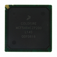
MCF5484CZP200 Freescale Semiconductor, MCF5484CZP200 Datasheet - Page 9

MCF5484CZP200
Manufacturer Part Number
MCF5484CZP200
Description
IC MPU 32BIT COLDF 388-PBGA
Manufacturer
Freescale Semiconductor
Series
MCF548xr
Datasheet
1.MCF5480CVR166.pdf
(34 pages)
Specifications of MCF5484CZP200
Core Processor
Coldfire V4E
Core Size
32-Bit
Speed
200MHz
Connectivity
CAN, EBI/EMI, Ethernet, I²C, SPI, UART/USART, USB
Peripherals
DMA, PWM, WDT
Number Of I /o
99
Program Memory Type
ROMless
Ram Size
32K x 8
Voltage - Supply (vcc/vdd)
1.43 V ~ 1.58 V
Oscillator Type
External
Operating Temperature
-40°C ~ 85°C
Package / Case
388-BGA
Program Memory Size
64KB
Cpu Speed
200MHz
Embedded Interface Type
I2C, UART, DMA
Digital Ic Case Style
BGA
No. Of Pins
388
Supply Voltage Range
3V To 3.6V, 1.43V To 1.58V
Rohs Compliant
No
For Use With
M5485EVBGHSE - KIT DEV GHS FOR M5485EVBM5485EVBGHS - KIT DEV GHS FOR M5485EVBM5485BFEE - MODULE MCF5485 FIRE ENGINEM5485AFEE - MODULE MCF5485 FIRE ENGINEM5485AFE - MODULE MCF5485 FIRE ENGINEM5484GFEE - MODULE M5484 FIRE ENGINEM5484LITEKITE - KIT DEV FOR MCF548X FAMILY
Lead Free Status / RoHS Status
Contains lead / RoHS non-compliant
Eeprom Size
-
Program Memory Size
-
Data Converters
-
Available stocks
Company
Part Number
Manufacturer
Quantity
Price
Company:
Part Number:
MCF5484CZP200
Manufacturer:
Exar
Quantity:
100
Company:
Part Number:
MCF5484CZP200
Manufacturer:
FREESCAL
Quantity:
185
Company:
Part Number:
MCF5484CZP200
Manufacturer:
Freescale Semiconductor
Quantity:
10 000
4.4
To minimize noise, an external filter is required for each of the USB power pins. The filter shown in
connected between the board EV
Table 5
Freescale Semiconductor
•
•
•
•
•
•
lists the resistor values and supply voltages to be used in the circuit for each of the USB V
The resistor and capacitors should be placed as close to the dedicated USB V
A separate filter circuit should be included for each USB V
All traces should be as low impedance as possible, especially ground pins to the ground plane.
The filter for USB_PHYVDD to VSS should be connected to the power and ground planes, respectively, not fingers
of the planes.
In addition to keeping the filter components for the USB_PLLVDD as close as practical to the body of the processor
as previously mentioned, special care should be taken to avoid coupling switching power supply noise or digital
switching noise onto the portion of that supply between the filter and the processor.
The capacitors for C2 in the table below should be rated X5R or better due to temperature performance.
USB Power Filtering
In addition to the above filter circuitry, a 0.01 F capacitor is also recommended in parallel
with those shown.
(Oscillator analog supply)
(Main transceiver supply)
(Bias generator supply)
(Oscillator supply)
USB_OSCAVDD
Board EV
USB_OSCVDD
USB_PHYVDD
USB_PLLVDD
USB V
(PLL supply)
USBVDD
DD
DD
DD
Pin
/IV
or IV
DD
MCF548x ColdFire
DD
Table 5. USB Filter Circuit Values
Figure 6. USB V
and each of the USB V
R1
Nominal Voltage
3.3V
3.3V
1.5V
3.3V
1.5V
NOTE
C1
®
Microprocessor, Rev. 4
GND
DD
Power Filter
DD
DD
pin, a total of five circuits.
pins.
R1 (Ω)
C2
10
10
0
0
0
DD
C1 (μF)
pin as possible.
USB V
Hardware Design Considerations
10
10
10
10
1
DD
DD
Pin
Figure 6
pins.
C2 (μF)
0.1
0.1
0.1
0.1
0.1
should be
9


