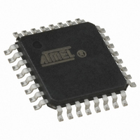
ATMEGA16U2-AU Atmel, ATMEGA16U2-AU Datasheet - Page 191

ATMEGA16U2-AU
Manufacturer Part Number
ATMEGA16U2-AU
Description
MCU AVR 16K FLASH USB 32TQFP
Manufacturer
Atmel
Series
AVR® ATmegar
Specifications of ATMEGA16U2-AU
Core Processor
AVR
Core Size
8-Bit
Speed
16MHz
Connectivity
SPI, UART/USART, USB
Peripherals
Brown-out Detect/Reset, POR, PWM, WDT
Number Of I /o
22
Program Memory Size
16KB (8K x 16)
Program Memory Type
FLASH
Eeprom Size
512 x 8
Ram Size
512 x 8
Voltage - Supply (vcc/vdd)
2.7 V ~ 5.5 V
Oscillator Type
Internal
Operating Temperature
-40°C ~ 85°C
Package / Case
32-TQFP, 32-VQFP
Processor Series
ATMEGA16x
Core
AVR8
Data Bus Width
8 bit
Data Ram Size
1.25 KB
Interface Type
SPI, UART
Maximum Clock Frequency
16 MHz
Number Of Programmable I/os
22
Number Of Timers
2
Maximum Operating Temperature
+ 85 C
Mounting Style
SMD/SMT
3rd Party Development Tools
EWAVR, EWAVR-BL
Development Tools By Supplier
ATAVRDRAGON, ATSTK500, ATSTK600, ATAVRISP2, ATAVRONEKIT, AT90USBKEY, ATEVK525
Minimum Operating Temperature
- 40 C
For Use With
ATSTK600 - DEV KIT FOR AVR/AVR32ATSTK500 - PROGRAMMER AVR STARTER KIT
Lead Free Status / RoHS Status
Lead free / RoHS Compliant
Data Converters
-
Lead Free Status / Rohs Status
Details
Available stocks
Company
Part Number
Manufacturer
Quantity
Price
- Current page: 191 of 309
- Download datasheet (6Mb)
20.5
20.5.1
20.5.2
7799D–AVR–11/10
Power modes
Idle mode
Power-down
UESTAX.6
UESTAX.5
UEINTX.6
UEINTX.4
UEINTX.3
UEINTX.2
UEINTX.1
UEINTX.0
UNDERFI
NAKOUTI
RXOUTI
STALLEDI
OVERFI
RXSTPI
NAKINI
TXINI
Figure 20-10. USB Endpoint Interrupt vector sources
Each endpoint has 8 interrupts sources associated with flags, and each source can be enabled
to trigger the corresponding endpoint interrupt.
If, for an endpoint, at least one of the sources is enabled to trigger interrupt, the corresponding
event(s) will make the program branch to the USB Endpoint Interrupt vector. The user may
determine the source (endpoint) of the interrupt by reading the
Register” on page
In Idle mode, the CPU is halted (CPU clock stopped). The Idle mode is taken wether the USB
controller is running or not. The CPU can wake up on any USB interrupts.
In Power-down mode, the oscillator is stopped and halts all the clocks (CPU and peripherals).
The USB controller wakes up when:
• the WAKEUPI interrupt is triggered (single asynchronous interrupt)
UEIENX.7
UEIENX.6
UEIENX.4
UEIENX.3
UEIENX.2
UEIENX.1
UEIENX.0
RXOUTE
STALLEDE
TXOUTE
FLERRE
TXSTPE
NAKINE
TXINE
210.
UEINT.X
Endpoint 0
EPINT
Endpoint 1
Endpoint 2
Endpoint 3
Endpoint 4
ATmega8U2/16U2/32U2
“UDINT – USB Device Interrupt
Interrupt Vec
USB Endpoi
191
Related parts for ATMEGA16U2-AU
Image
Part Number
Description
Manufacturer
Datasheet
Request
R

Part Number:
Description:
Manufacturer:
Atmel Corporation
Datasheet:

Part Number:
Description:
IC AVR MCU 16K 16MHZ 5V 44TQFP
Manufacturer:
Atmel
Datasheet:

Part Number:
Description:
IC AVR MCU 16K 16MHZ 5V 44-QFN
Manufacturer:
Atmel
Datasheet:

Part Number:
Description:
IC AVR MCU 16K 16MHZ 5V 40DIP
Manufacturer:
Atmel
Datasheet:

Part Number:
Description:
MCU AVR 16K FLASH 16MHZ 44-QFN
Manufacturer:
Atmel
Datasheet:

Part Number:
Description:
IC AVR MCU 16K 16MHZ COM 40-DIP
Manufacturer:
Atmel
Datasheet:

Part Number:
Description:
IC AVR MCU 16K 16MHZ COM 44-QFN
Manufacturer:
Atmel
Datasheet:

Part Number:
Description:
IC AVR MCU 16K 16MHZ IND 40-DIP
Manufacturer:
Atmel
Datasheet:

Part Number:
Description:
IC AVR MCU 16K 16MHZ IND 44-QFN
Manufacturer:
Atmel
Datasheet:

Part Number:
Description:
IC AVR MCU 16K 16MHZ IND 44-TQFP
Manufacturer:
Atmel
Datasheet:

Part Number:
Description:
IC MCU 8BIT 16KB FLASH 44TQFP
Manufacturer:
Atmel
Datasheet:

Part Number:
Description:
MCU AVR 16K FLASH 16MHZ 44-TQFP
Manufacturer:
Atmel
Datasheet:

Part Number:
Description:
IC AVR MCU 16K 16MHZ COM 44-TQFP
Manufacturer:
Atmel
Datasheet:


