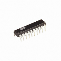
ATTINY26-16PU Atmel, ATTINY26-16PU Datasheet - Page 82

ATTINY26-16PU
Manufacturer Part Number
ATTINY26-16PU
Description
IC AVR MCU 2K 16MHZ IND 20-DIP
Manufacturer
Atmel
Series
AVR® ATtinyr
Specifications of ATTINY26-16PU
Core Processor
AVR
Core Size
8-Bit
Speed
16MHz
Connectivity
USI
Peripherals
Brown-out Detect/Reset, POR, PWM, WDT
Number Of I /o
16
Program Memory Size
2KB (1K x 16)
Program Memory Type
FLASH
Eeprom Size
128 x 8
Ram Size
128 x 8
Voltage - Supply (vcc/vdd)
4.5 V ~ 5.5 V
Data Converters
A/D 11x10b
Oscillator Type
Internal
Operating Temperature
-40°C ~ 85°C
Package / Case
20-DIP (0.300", 7.62mm)
Processor Series
ATTINY2x
Core
AVR8
Data Bus Width
8 bit
Data Ram Size
128 B
Interface Type
2-Wire/ISP/SM-Bus/SPI/UART/USI
Maximum Clock Frequency
16 MHz
Number Of Programmable I/os
16
Number Of Timers
2
Operating Supply Voltage
4.5 V to 5.5 V
Maximum Operating Temperature
+ 85 C
Mounting Style
Through Hole
3rd Party Development Tools
EWAVR, EWAVR-BL
Development Tools By Supplier
ATAVRDRAGON, ATSTK500, ATSTK600, ATAVRISP2, ATAVRONEKIT
Minimum Operating Temperature
- 40 C
On-chip Adc
11-ch x 10-bit
Package
20PDIP
Device Core
AVR
Family Name
ATtiny
Maximum Speed
16 MHz
For Use With
ATSTK600 - DEV KIT FOR AVR/AVR32770-1007 - ISP 4PORT ATMEL AVR MCU SPI/JTAGATAVRISP2 - PROGRAMMER AVR IN SYSTEMATSTK505 - ADAPTER KIT FOR 14PIN AVR MCU
Lead Free Status / RoHS Status
Lead free / RoHS Compliant
USI Control Register –
USICR
82
ATtiny26(L)
• Bit 5 – USIPF: Stop Condition Flag
When Two-wire mode is selected, the USIPF flag is set (one) when a stop condition is detected.
The flag is cleared by writing a one to this bit. Note that this is not an interrupt flag. This signal is
useful when implementing Two-wire bus master arbitration.
• Bit 4 – USIDC: Data Output Collision
This bit is logical one when bit 7 in the Shift Register differs from the physical pin value. The flag
is only valid when Two-wire mode is used. This signal is useful when implementing Two-wire
bus master arbitration.
• Bits 3..0 – USICNT3..0: Counter Value
These bits reflect the current 4-bit counter value. The 4-bit counter value can directly be read or
written by the CPU.
The 4-bit counter increments by one for each clock generated either by the external clock edge
detector, by a Timer/Counter0 overflow, or by software using USICLK or USITC strobe bits. The
clock source depends of the setting of the USICS1..0 bits. For external clock operation a special
feature is added that allows the clock to be generated by writing to the USITC strobe bit. This
feature is enabled by write a one to the USICLK bit while setting an external clock source
(USICS1 = 1).
Note that even when no wire mode is selected (USIWM1..0 = 0) the external clock input
(SCK/SCL) are can still be used by the counter.
The Control Register includes interrupt enable control, wire mode setting, clock select setting,
and clock strobe.
• Bit 7 – USISIE: Start Condition Interrupt Enable
Setting this bit to one enables the Start Condition detector interrupt. If there is a pending inter-
rupt when the USISIE and the Global Interrupt Enable Flag is set to one, this will immediately be
executed. Refer to the description of “Bit 7 – USISIF: Start Condition Interrupt Flag” on page 81
for further details.
When Two-wire mode is selected, the USISIF flag is set (to one) when a start condition is
detected. When output disable mode or Three-wire mode is selected and (USICSx = 0b11 &
USICLK = 0) or (USICS = 0b10 & USICLK = 0), any edge on the SCK pin sets the flag.
• Bit 6 – USIOIE: Counter Overflow Interrupt Enable
Setting this bit to one enables the Counter Overflow interrupt. If there is a pending interrupt when
the USIOIE and the Global Interrupt Enable Flag is set to one, this will immediately be executed.
Refer to the description of “Bit 6 – USIOIF: Counter Overflow Interrupt Flag” on page 81 for fur-
ther details.
Bit
$0D ($2D)
Read/Write
Initial Value
USISIE
R/W
7
0
USIOIE
R/W
6
0
USIWM1
R/W
5
0
USIWM0
R/W
4
0
USICS1
R/W
3
0
USICS0
R/W
2
0
USICLK
W
1
0
USITC
W
0
0
1477K–AVR–08/10
USICR


