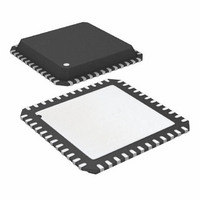
ATA6613P-PLPW Atmel, ATA6613P-PLPW Datasheet - Page 156

ATA6613P-PLPW
Manufacturer Part Number
ATA6613P-PLPW
Description
MCU W/LIN TXRX REG WTCHDG 48-QFN
Manufacturer
Atmel
Series
AVR® ATA66 LIN-SBCr
Datasheet
1.ATA6612-EK.pdf
(364 pages)
Specifications of ATA6613P-PLPW
Core Processor
AVR
Core Size
8-Bit
Speed
16MHz
Connectivity
I²C, LIN, SPI, UART/USART
Peripherals
Brown-out Detect/Reset, POR, PWM, WDT
Number Of I /o
23
Program Memory Size
16KB (16K x 8)
Program Memory Type
FLASH
Eeprom Size
512 x 8
Ram Size
1K x 8
Voltage - Supply (vcc/vdd)
2.7 V ~ 5.5 V
Data Converters
A/D 8x10b
Oscillator Type
Internal
Operating Temperature
-40°C ~ 125°C
Package / Case
48-QFN Exposed Pad
Processor Series
ATA6x
Core
AVR8
Data Bus Width
8 bit
Data Ram Size
1 KB
Interface Type
SPI, TWI, USART
Maximum Clock Frequency
16 MHz
Number Of Programmable I/os
23
Number Of Timers
3
Maximum Operating Temperature
+ 125 C
Mounting Style
SMD/SMT
Minimum Operating Temperature
- 40 C
On-chip Adc
10 bit, 8 Channel
Lead Free Status / RoHS Status
Lead free / RoHS Compliant
- Current page: 156 of 364
- Download datasheet (7Mb)
156
Atmel ATA6612/ATA6613
Table 6-55
correct or the phase and frequency correct, PWM mode.
Table 6-55.
Note:
• Bit 1:0 – WGM11:0: Waveform Generation Mode
COM1A1/COM1B1
Combined with the WGM13:2 bits found in the TCCR1B Register, these bits control the
counting sequence of the counter, the source for maximum (TOP) counter value, and what
type of waveform generation to be used (see
tion supported by the Timer/Counter unit are: Normal mode (counter), Clear Timer on
Compare match (CTC) mode, and three types of Pulse Width Modulation (PWM) modes
(see
1. A special case occurs when OCR1A/OCR1B equals TOP and COM1A1/COM1B1 is set.
“Modes of Operation” on page
0
0
1
1
shows the COM1x1:0 bit functionality when the WGM13:0 bits are set to the phase
See
Compare Output Mode, Phase Correct and Phase and Frequency Correct
PWM
“Phase Correct PWM Mode” on page 149
(1)
COM1A0/COM1B0
0
1
0
1
145).
Description
Normal port operation, OC1A/OC1B disconnected.
WGM13:0 = 8, 9, 10 or 11: Toggle OC1A on Compare
Match, OC1B disconnected (normal port operation). For
all other WGM1 settings, normal port operation,
OC1A/OC1B disconnected.
Clear OC1A/OC1B on Compare Match when
up-counting. Set OC1A/OC1B on Compare Match when
downcounting.
Set OC1A/OC1B on Compare Match when up-counting.
Clear OC1A/OC1B on Compare Match when
downcounting.
Table 6-56 on page
for more details.
157). Modes of opera-
9111H–AUTO–01/11
Related parts for ATA6613P-PLPW
Image
Part Number
Description
Manufacturer
Datasheet
Request
R

Part Number:
Description:
MCU W/LIN TXRX REG WTCHDG 48-QFN
Manufacturer:
Atmel
Datasheet:

Part Number:
Description:
Ata6613
Manufacturer:
ATMEL Corporation
Datasheet:

Part Number:
Description:
BOARD DEMO LIN-MCM FOR ATA6613
Manufacturer:
Atmel
Datasheet:

Part Number:
Description:
DEV KIT FOR AVR/AVR32
Manufacturer:
Atmel
Datasheet:

Part Number:
Description:
INTERVAL AND WIPE/WASH WIPER CONTROL IC WITH DELAY
Manufacturer:
ATMEL Corporation
Datasheet:

Part Number:
Description:
Low-Voltage Voice-Switched IC for Hands-Free Operation
Manufacturer:
ATMEL Corporation
Datasheet:

Part Number:
Description:
MONOLITHIC INTEGRATED FEATUREPHONE CIRCUIT
Manufacturer:
ATMEL Corporation
Datasheet:

Part Number:
Description:
AM-FM Receiver IC U4255BM-M
Manufacturer:
ATMEL Corporation
Datasheet:

Part Number:
Description:
Monolithic Integrated Feature Phone Circuit
Manufacturer:
ATMEL Corporation
Datasheet:

Part Number:
Description:
Multistandard Video-IF and Quasi Parallel Sound Processing
Manufacturer:
ATMEL Corporation
Datasheet:

Part Number:
Description:
High-performance EE PLD
Manufacturer:
ATMEL Corporation
Datasheet:

Part Number:
Description:
8-bit Flash Microcontroller
Manufacturer:
ATMEL Corporation
Datasheet:


