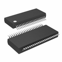
ATMEGA32HVB-8X3 Atmel, ATMEGA32HVB-8X3 Datasheet

ATMEGA32HVB-8X3
Specifications of ATMEGA32HVB-8X3
Available stocks
Related parts for ATMEGA32HVB-8X3
ATMEGA32HVB-8X3 Summary of contents
Page 1
... Maximum Withstand Voltage (High-voltage pins): 35V • Temperature Range: -40°C to 85°C • Speed Grade: 1-8 MHz Note: 1. See ”Data Retention” on page 8 ® 8-bit Microcontroller (1) for details. 8-bit Microcontroller with 16K/32K Bytes In-System Programmable Flash ATmega16HVB ATmega32HVB Preliminary Summary 8042B–AVR–06/10 ...
Page 2
Pin Configurations 1.1 TSSOP Figure 1-1. PA0(ADC0/SGND/PCINT0) PA1(ADC1/SGND/PCINT1) 1.2 Pin Descriptions 1.2.1 VFET High voltage supply pin. This pin is used as supply for the internal voltage regulator, described in ”Voltage Regulator” on page 1.2.2 VCC Digital supply voltage. ...
Page 3
VREF Internal Voltage Reference for external decoupling. For details, see Temperature Sensor” on page 1.2.5 VREFGND Ground for decoupling of Internal Voltage Reference. For details, see Temperature Sensor” on page 1.2.6 GND Ground 1.2.7 Port A (PA3..PA0) Port A ...
Page 4
PPI/NNI Unfiltered positive/negative input from external current sense resistor, used by the battery pro- tection circuit, for over-current and short-circuit detection. For details, see page 133. 1.2.14 NV/PV1/PV2/PV3/PV4 NV, PV1, PV2, PV3, and PV4 are the inputs for battery ...
Page 5
Overview The ATmega16HVB/32HVB is a monitoring and protection circuit for 3 and 4-cell Li-ion applica- tions with focus on highest safety including safe authentication, low cost and high utilization of the cell energy. The device contains secure authentication features ...
Page 6
... CISC microcontrollers. The device is manufactured using Atmel’s high voltage high density non-volatile memory tech- nology. The On-chip ISP Flash allows the program memory to be reprogrammed In-System, through an SPI serial interface conventional non-volatile memory programmer On- chip Boot program running on the AVR core ...
Page 7
... Comparison Between ATmega16HVB and ATmega32HVB The ATmega16HVB and ATmega32HVB differ only in memory size for Flash, EEPROM and internal SRAM. Table 2-1. 8042B–AVR–06/10 Table 2-1 summarizes the different configuration for the two devices. Configuration summary Device Flash ATmega16HVB 16K ...
Page 8
... Final values will be available after the device is characterized. 4. Resources A comprehensive set of development tools, application notes and datasheets are available for download on http://www.atmel.com/avr.n1 Note: 5. About Code Examples This documentation contains simple code examples that briefly show how to use various parts of the device ...
Page 9
Register Summary Address Name Bit 7 (0xFF) Reserved – (0xFE) BPPLR – (0xFD) BPCR – (0xFC) BPHCTR – (0xFB) BPOCTR – (0xFA) BPSCTR – (0xF9) BPCHCD (0xF8) BPDHCD (0xF7) BPCOCD (0xF6) BPDOCD (0xF5) BPSCD (0xF4) Reserved – (0xF3) BPIFR ...
Page 10
Address Name Bit 7 (0xBF) Reserved – (0xBE) TWBCSR TWBCIF (0xBD) TWAMR (0xBC) TWCR TWINT (0xBB) TWDR (0xBA) TWAR (0xB9) TWSR (0xB8) TWBR (0xB7) Reserved – (0xB6) Reserved – (0xB5) Reserved – (0xB4) Reserved – (0xB3) Reserved – (0xB2) Reserved ...
Page 11
Address Name Bit 7 (0x7D) Reserved – (0x7C) VADMUX – (0x7B) Reserved – (0x7A) VADCSR – (0x79) VADCH – (0x78) VADCL (0x77) Reserved – (0x76) Reserved – (0x75) Reserved – (0x74) Reserved – (0x73) Reserved – (0x72) Reserved – (0x71) ...
Page 12
Address Name Bit 7 0x1B (0x3B) PCIFR – 0x1A (0x3A) Reserved – 0x19 (0x39) Reserved – 0x18 (0x38) Reserved – 0x17 (0x37) OSICSR – 0x16 (0x36) TIFR1 – 0x15 (0x35) TIFR0 – 0x14 (0x34) Reserved – 0x13 (0x33) Reserved – ...
Page 13
Instruction Set Summary Mnemonics Operands ARITHMETIC AND LOGIC INSTRUCTIONS ADD Rd, Rr Add two Registers ADC Rd, Rr Add with Carry two Registers ADIW Rdl,K Add Immediate to Word SUB Rd, Rr Subtract two Registers SUBI Rd, K Subtract ...
Page 14
Instruction Set Summary (Continued) Mnemonics Operands BRIE k Branch if Interrupt Enabled BRID k Branch if Interrupt Disabled BIT AND BIT-TEST INSTRUCTIONS SBI P,b Set Bit in I/O Register CBI P,b Clear Bit in I/O Register LSL Rd Logical ...
Page 15
Instruction Set Summary (Continued) Mnemonics Operands OUT P, Rr Out Port PUSH Rr Push Register on Stack POP Rd Pop Register from Stack MCU CONTROL INSTRUCTIONS NOP No Operation SLEEP Sleep WDR Watchdog Reset BREAK Break 8042B–AVR–06/10 Description P ...
Page 16
Ordering Information 9.1 ATmega16HVB Speed (MHz) Power Supply MHz 4 - 25V 44X1 44-lead, 4.4 mm Body Width, Plastic Thin Shrink Small Outline Package (TSSOP) 8042B–AVR–06/10 ATmega16HVB/32HVB Ordering Code Package ATMEGA16HVB-8X3 44X1 Package Type Operation Range ...
Page 17
... ATmega32HVB Speed (MHz) Power Supply MHz 4 - 25V 44X1 44-lead, 4.4 mm Body Width, Plastic Thin Shrink Small Outline Package (TSSOP) 8042B–AVR–06/10 ATmega16HVB/32HVB Ordering Code Package ATMEGA32HVB-8X3 44X1 Package Type Operation Range -40°C to 85°C 17 ...
Page 18
Packaging Information 10.1 44X1 Top View Top View Side View Side View Note: These drawings are for general information only. Refer to JEDEC Drawing MO-153BE. Note: These drawings are for general information only. Refer to ...
Page 19
... Errata 11.1 ATmega16HVB 11.1.1 Rev known errata. 11.2 ATmega32HVB 11.2.1 Rev known errata. 8042B–AVR–06/10 ATmega16HVB/32HVB 19 ...
Page 20
Revision history Please note that the referring page numbers in this section are referring to this document. The referring revision in this section are referring to the document revision. 12.1 Rev. 8042B–06/10 1. 12.2 Rev. 8042A–08/09 1. 8042B–AVR–06/10 Removed ...
Page 21
... Disclaimer: The information in this document is provided in connection with Atmel products. No license, express or implied, by estoppel or otherwise, to any intellectual property right is granted by this document or in connection with the sale of Atmel products. EXCEPT AS SET FORTH IN ATMEL’S TERMS AND CONDI- TIONS OF SALE LOCATED ON ATMEL’S WEB SITE, ATMEL ASSUMES NO LIABILITY WHATSOEVER AND DISCLAIMS ANY EXPRESS, IMPLIED OR STATUTORY WARRANTY RELATING TO ITS PRODUCTS INCLUDING, BUT NOT LIMITED TO, THE IMPLIED WARRANTY OF MERCHANTABILITY, FITNESS FOR A PARTICULAR PURPOSE, OR NON-INFRINGEMENT ...


