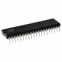
P87C51RC2BN,112 NXP Semiconductors, P87C51RC2BN,112 Datasheet - Page 14

P87C51RC2BN,112
Manufacturer Part Number
P87C51RC2BN,112
Description
IC 80C51 MCU 512 RAM 40DIP
Manufacturer
NXP Semiconductors
Series
87Cr
Datasheet
1.P87C51RC2FA512.pdf
(67 pages)
Specifications of P87C51RC2BN,112
Core Processor
8051
Core Size
8-Bit
Speed
33MHz
Connectivity
EBI/EMI, UART/USART
Peripherals
POR, PWM, WDT
Number Of I /o
32
Program Memory Size
32KB (32K x 8)
Program Memory Type
OTP
Ram Size
512 x 8
Voltage - Supply (vcc/vdd)
2.7 V ~ 5.5 V
Oscillator Type
Internal
Operating Temperature
0°C ~ 70°C
Package / Case
40-DIP (0.600", 15.24mm)
Cpu Family
87C
Device Core
80C51
Device Core Size
8b
Frequency (max)
33MHz
Interface Type
UART
Total Internal Ram Size
512Byte
# I/os (max)
32
Number Of Timers - General Purpose
3
Operating Supply Voltage (typ)
3.3/5V
Operating Supply Voltage (max)
5.5V
Operating Supply Voltage (min)
2.7V
Instruction Set Architecture
CISC
Operating Temp Range
0C to 70C
Operating Temperature Classification
Commercial
Mounting
Through Hole
Pin Count
40
Package Type
PDIP
Processor Series
P87C5x
Core
80C51
Data Bus Width
8 bit
Maximum Clock Frequency
16 MHz
Operating Supply Voltage
2.7 V to 5.5 V
Maximum Operating Temperature
+ 70 C
Mounting Style
SMD/SMT
3rd Party Development Tools
PK51, CA51, A51, ULINK2
Minimum Operating Temperature
0 C
For Use With
OM10064 - EMULATOR 80C51 PDS51-MK2
Lead Free Status / RoHS Status
Lead free / RoHS Compliant
Eeprom Size
-
Data Converters
-
Lead Free Status / Rohs Status
Compliant
Other names
935272150112
P87C51RC2BN
P87C51RC2BN
P87C51RC2BN
P87C51RC2BN
Philips Semiconductors
2003 Jan 24
80C51 8-bit microcontroller family
with 512B/1KB RAM, low voltage (2.7 to 5.5 V), low power, high
speed (30/33 MHz)
TCON
*d = 6 in 6-clock mode; d = 12 in 12-clock mode.
Timer n
Gate bit
INTn Pin
BIT
TCON.7
TCON.6
TCON.5
TCON.4
TCON.3
TCON.2
TCON.1
TCON.0
OSC
Address = 88H
Bit Addressable
Tn Pin
SYMBOL
TF1
TR1
TF0
TR0
IE1
IT1
IE0
IT0
TRn
d*
TF1
FUNCTION
Timer 1 overflow flag. Set by hardware on Timer/Counter overflow.
Cleared by hardware when processor vectors to interrupt routine, or clearing the bit in software.
Timer 1 Run control bit. Set/cleared by software to turn Timer/Counter on/off.
Timer 0 overflow flag. Set by hardware on Timer/Counter overflow.
Cleared by hardware when processor vectors to interrupt routine, or by clearing the bit in software.
Timer 0 Run control bit. Set/cleared by software to turn Timer/Counter on/off.
Interrupt 1 Edge flag. Set by hardware when external interrupt edge detected.
Cleared when interrupt processed.
Interrupt 1 type control bit. Set/cleared by software to specify falling edge/low level triggered
external interrupts.
Interrupt 0 Edge flag. Set by hardware when external interrupt edge detected.
Cleared when interrupt processed.
Interrupt 0 Type control bit. Set/cleared by software to specify falling edge/low level
triggered external interrupts.
7
Figure 3. Timer/Counter 0/1 Mode 0: 13-Bit Timer/Counter
Figure 4. Timer/Counter 0/1 Control (TCON) Register
TR1
8KB/16KB/32KB/64KB OTP
6
C/T = 0
C/T = 1
TF0
5
TR0
4
Control
14
IE1
3
IT1
2
(5 Bits)
TLn
P87C51RA2/RB2/RC2/RD2
IE0
1
(8 Bits)
THn
IT0
0
Reset Value = 00H
TFn
SU01618
Interrupt
SU01516
Product data


