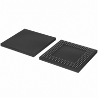
LPC3180FEL320/01,5 NXP Semiconductors, LPC3180FEL320/01,5 Datasheet - Page 10

LPC3180FEL320/01,5
Manufacturer Part Number
LPC3180FEL320/01,5
Description
IC ARM9 MCU 208MHZ 320-LFBGA
Manufacturer
NXP Semiconductors
Series
LPC3000r
Specifications of LPC3180FEL320/01,5
Package / Case
320-LFBGA
Core Processor
ARM9
Core Size
16/32-Bit
Speed
208MHz
Connectivity
EBI/EMI, I²C, MMC, SPI, UART/USART, USB OTG
Peripherals
DMA, PWM, WDT
Number Of I /o
55
Program Memory Type
ROMless
Ram Size
64K x 8
Voltage - Supply (vcc/vdd)
1.1 V ~ 3.3 V
Data Converters
A/D 3x10b
Oscillator Type
External
Operating Temperature
-40°C ~ 85°C
Processor Series
LPC31
Core
ARM926EJ-S
Data Bus Width
32 bit
Maximum Clock Frequency
208 MHz
Operating Supply Voltage
1.8 V / 3V
Maximum Operating Temperature
+ 85 C
Mounting Style
SMD/SMT
3rd Party Development Tools
MDK-ARM, RL-ARM, ULINK2
Development Tools By Supplier
OM10096
Minimum Operating Temperature
- 40 C
Package
320LFBGA
Device Core
ARM926EJ-S
Family Name
LPC3100
Maximum Speed
208 MHz
Number Of Programmable I/os
55
Interface Type
I2C/SPI/UART/USB
On-chip Adc
3-chx10-bit
Number Of Timers
2
Lead Free Status / RoHS Status
Lead free / RoHS Compliant
For Use With
622-1018 - EVAL KIT FOR LP3180568-4063 - KIT DEV LPC3180568-4062 - DEBUGGER J-LINK JTAG568-4061 - DEBUGGER U-LINK2 JTAG FOR NXP
Eeprom Size
-
Program Memory Size
-
Lead Free Status / Rohs Status
Lead free / RoHS Compliant
Other names
568-4529
935286983551
935286983551
Available stocks
Company
Part Number
Manufacturer
Quantity
Price
Company:
Part Number:
LPC3180FEL320/01,5
Manufacturer:
NXP Semiconductors
Quantity:
10 000
NXP Semiconductors
Table 3.
LPC3180_2
Preliminary data sheet
Symbol
KEY_COL0 to
KEY_COL5
KEY_ROW0 to
KEY_ROW5
MS_BS
MS_DIO0 to MS_DIO3
MS_SCLK
ONSW
PLL397_LOOP
PWM_OUT1
PWM_OUT2
RAM_A[14:00]
RAM_CAS_N
RAM_CKE
RAM_CLK
RAM_CLKIN
RAM_CS_N
RAM_D[15:00]
RAM_D[16]/
DDR_DQS0
RAM_D[17]/
DDR_DQS1
RAM_D[18]/
DDR_NCLK
RAM_D[31:19]/
PIO_SD[12:00]
RAM_DQM[3:0]
RAM_RAS_N
RAM_WR_N
RESET_N
RESOUT_N
RTCX_IN
RTCX_OUT
Pin description
Pin
D2, F4, C1, C2, E4,
B1
G3, F2, E1, F3, D1,
E2
Y1
W2, U2, Y2, V4
AA1
D12
C21
J2
H3
W21, AA24, Y23,
AB24, Y22, AA23,
AB23, AB22, AC23,
AA21, AC22, AD24,
AD23, AB20, AD22
V23
U24
U23
T21
V24
L24, M23, L22,
M24, N23, M22,
N24, P23, N21,
P24, R23, P21,
R24, T24, T22, T23
L23
L21
K24
E24, E23, F21, F24,
G24, H23, J21,
G23, H22, K23,
H24, J24, H21
W24, V21, W23,
Y24
U21
V22
D13
AB12
A14
A13
…continued
Rev. 02 — 15 February 2007
Type Description
I
O
I/O
I/O
O
O
I/O
O
O
O
O
O
O
I
O
I/O
I/O
O
I/O
O
I/O
O
I/O
I/O
O
O
O
I
O
I
O
16/32-bit ARM microcontroller with external memory interface
keyboard scan column inputs
keyboard scan row outputs 0 through 5
SD card command input/output (SD_CMD)
SD card data bus (SD_D0 to SD_D3)
SD card clock output (SD_CLK)
VCCon output signal
loop filter pin for PLL397; requires external components if PLL397
is used
output of Pulse Width Modulator 1
output of Pulse Width Modulator 2
SDRAM address bus, pins 14 to 00
SDRAM column address strobe output
SDRAM clock enable output
SDRAM clock output
SDRAM clock return input
SDRAM chip select output
SDRAM data bus, pins 15 to 00
RAM_D[16] — SDRAM data bus, pin 16
DDR_DQS0 — SDRAM data strobe output for lower byte
RAM_D[17] — SDRAM data bus, pin 17
DDR_DQS1 — SDRAM data strobe output for upper byte
RAM_D[18] — SDRAM data bus, pin 18
DDR_NCLK — inverted SDRAM clock output for DDR
RAM_D[31:19] — SDRAM data bus, pins 31 to 19
PIO_SD[12:00] — general purpose input/output, pins 12 to 00;
details may be found in
I/O” on page 18
SDRAM byte write mask outputs
SDRAM row address strobe output
SDRAM write strobe output
system reset input
reset output signal
RTC oscillator input
RTC oscillator output
Section 6.10 “General purpose parallel
LPC3180
© NXP B.V. 2007. All rights reserved.
10 of 36


