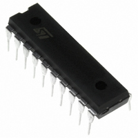
ST7FLITE35F2B6 STMicroelectronics, ST7FLITE35F2B6 Datasheet - Page 111

ST7FLITE35F2B6
Manufacturer Part Number
ST7FLITE35F2B6
Description
IC MCU 8BIT 8K FLASH 20DIP
Manufacturer
STMicroelectronics
Series
ST7r
Specifications of ST7FLITE35F2B6
Core Processor
ST7
Core Size
8-Bit
Speed
8MHz
Connectivity
LINSCI, SPI
Peripherals
LVD, POR, PWM, WDT
Number Of I /o
15
Program Memory Size
8KB (8K x 8)
Program Memory Type
FLASH
Ram Size
384 x 8
Voltage - Supply (vcc/vdd)
2.7 V ~ 5.5 V
Data Converters
A/D 7x10b
Oscillator Type
Internal
Operating Temperature
-40°C ~ 85°C
Package / Case
20-DIP (0.300", 7.62mm)
Processor Series
ST7FLITE3x
Core
ST7
Data Bus Width
8 bit
Data Ram Size
384 B
Interface Type
LINSCI, SPI
Maximum Clock Frequency
8 MHz
Number Of Programmable I/os
15
Number Of Timers
4
Maximum Operating Temperature
+ 85 C
Mounting Style
Through Hole
Development Tools By Supplier
ST7FLITE-SK/RAIS, ST7MDT10-DVP3, ST7MDT10-EMU3, STX-RLINK
Minimum Operating Temperature
- 40 C
On-chip Adc
10 bit, 7 Channel
For Use With
497-5858 - EVAL BOARD PLAYBACK ST7FLITE497-5085 - EVAL BOARD UNIV MOTOR CONTROL497-5049 - KIT STARTER RAISONANCE ST7FLITE
Lead Free Status / RoHS Status
Lead free / RoHS Compliant
Eeprom Size
-
Lead Free Status / Rohs Status
Details
LINSCI™ SERIAL COMMUNICATION INTERFACE (LIN Mode) (cont’d)
11.5.9.5 LIN Baud Rate
Baud rate programming is done by writing a value
in the LPR prescaler or performing an automatic
resynchronization as described below.
Automatic Resynchronization
To automatically adjust the baud rate based on
measurement of the LIN Synch Field:
– Write the nominal LIN Prescaler value (usually
– Set the LASE bit to enable the Auto Synchroni-
When Auto Synchronization is enabled, after each
LIN Synch Break, the time duration between five
falling edges on RDI is sampled on f
result of this measurement is stored in an internal
15-bit register called SM (not user accessible)
(see
sociated LPFR and LPR registers) are automati-
cally updated at the end of the fifth falling edge.
During LIN Synch field measurement, the SCI
state machine is stopped and no data is trans-
ferred to the data register.
11.5.9.6 LIN Slave Baud Rate Generation
In LIN mode, transmission and reception are driv-
en by the LIN baud rate generator
Note: LIN Master mode uses the Extended or
Conventional prescaler register to generate the
baud rate.
If LINE bit = 1 and LSLV bit = 1 then the Conven-
tional and Extended Baud Rate Generators are
disabled: the baud rate for the receiver and trans-
depending on the nominal baud rate) in the
LPFR / LPR registers.
zation Unit.
Figure
61). Then the LDIV value (and its as-
CPU
and the
mitter are both set to the same value, depending
on the LIN Slave baud rate generator:
with:
LDIV is an unsigned fixed point number. The man-
tissa is coded on 8 bits in the LPR register and the
fraction is coded on 4 bits in the LPFR register.
If LASE bit = 1 then LDIV is automatically updated
at the end of each LIN Synch Field.
Three registers are used internally to manage the
auto-update of the LIN divider (LDIV):
- LDIV_NOM (nominal value written by software at
LPR/LPFR addresses)
- LDIV_MEAS (results of the Field Synch meas-
urement)
- LDIV (used to generate the local baud rate)
The control and interactions of these registers, ex-
plained in
LDUM bit setting (LIN Divider Update Method).
Note:
As explained in
be updated by two concurrent actions: a transfer
from LDIV_MEAS at the end of the LIN Sync Field
and a transfer from LDIV_NOM due to a software
write of LPR. If both operations occur at the same
time, the transfer from LDIV_NOM has priority.
Figure 62
Tx = Rx =
Figure 62
and
(16
Figure
f
and
CPU
*
LDIV)
Figure
63, depend on the
ST7LITE3xF2
63, LDIV can
111/173


