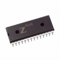
Z8F0422PJ020EG Zilog, Z8F0422PJ020EG Datasheet - Page 155

Z8F0422PJ020EG
Manufacturer Part Number
Z8F0422PJ020EG
Description
IC ENCORE MCU FLASH 4K 28DIP
Manufacturer
Zilog
Series
Encore!® XP®r
Datasheet
1.Z8F08200100KIT.pdf
(264 pages)
Specifications of Z8F0422PJ020EG
Core Processor
Z8
Core Size
8-Bit
Speed
20MHz
Connectivity
I²C, IrDA, SPI, UART/USART
Peripherals
Brown-out Detect/Reset, POR, PWM, WDT
Number Of I /o
19
Program Memory Size
4KB (4K x 8)
Program Memory Type
FLASH
Ram Size
1K x 8
Voltage - Supply (vcc/vdd)
2.7 V ~ 3.6 V
Data Converters
A/D 5x10b
Oscillator Type
Internal
Operating Temperature
-40°C ~ 105°C
Package / Case
28-DIP (0.600", 15.24mm)
Processor Series
Z8F042xx
Core
eZ8
Data Bus Width
8 bit
Data Ram Size
1 KB
Interface Type
I2C, SPI, UART
Maximum Clock Frequency
20 MHz
Number Of Programmable I/os
19
Number Of Timers
2
Operating Supply Voltage
2.7 V to 3.6 V
Maximum Operating Temperature
+ 105 C
Mounting Style
Through Hole
Minimum Operating Temperature
- 40 C
On-chip Adc
10 bit, 5 Channel
Lead Free Status / RoHS Status
Lead free / RoHS Compliant
Eeprom Size
-
Lead Free Status / Rohs Status
Details
Other names
269-4140
Z8F0422PJ020EG
Z8F0422PJ020EG
Available stocks
Company
Part Number
Manufacturer
Quantity
Price
Company:
Part Number:
Z8F0422PJ020EGR551H
Manufacturer:
ZILOG-PBF
Quantity:
9 045
- Current page: 155 of 264
- Download datasheet (6Mb)
PS022517-0508
set, this bit is reset by the I
the IEN bit. If this bit is 1, it cannot be cleared to 0 by writing to the register.
BIRQ—Baud Rate Generator Interrupt Request
This bit allows the I
Controller is disabled. This bit is ignored when the I
1 = An interrupt occurs every time the BRG counts down to one.
0 = No BRG interrupt occurs.
TXI—Enable TDRE interrupts
This bit enables the transmit interrupt when the I
1 = Transmit Interrupt (and DMA transmit request) is enabled.
0 = Transmit Interrupt (and DMA transmit request) is disabled.
NAK—Send NAK
This bit sends a Not Acknowledge condition after the next byte of data is read from the
I
deasserted. If this bit is 1, it cannot be cleared to 0 by writing to the register.
FLUSH—Flush Data
Setting this bit to 1 clears the I
flushing of the I
data has been sent to the I
FILTEN—I
This bit enables low-pass digital filters on the SDA and SCL input signals. These filters
reject any input pulse with periods less than a full system clock cycle. The filters introduce
a 3-system clock cycle latency on the inputs.
1 = low-pass filters are enabled.
0 = low-pass filters are disabled.
2
C Slave. Once asserted, it is deasserted after a Not Acknowledge is sent or the IEN bit is
2
C Signal Filter Enable
2
C Data Register when a Not Acknowledge interrupt is received after the
2
C Controller to be used as an additional timer when the I
2
2
C Data Register. Reading this bit always returns 0.
C Controller after a STOP condition is sent or by deasserting
2
C Data Register and sets the TDRE bit to 1. This bit allows
2
C Data Register is empty (TDRE = 1).
2
C Controller is enabled.
Z8 Encore! XP
Product Specification
®
F0822 Series
I2C Controller
2
C
142
Related parts for Z8F0422PJ020EG
Image
Part Number
Description
Manufacturer
Datasheet
Request
R

Part Number:
Description:
Communication Controllers, ZILOG INTELLIGENT PERIPHERAL CONTROLLER (ZIP)
Manufacturer:
Zilog, Inc.
Datasheet:

Part Number:
Description:
KIT DEV FOR Z8 ENCORE 16K TO 64K
Manufacturer:
Zilog
Datasheet:

Part Number:
Description:
KIT DEV Z8 ENCORE XP 28-PIN
Manufacturer:
Zilog
Datasheet:

Part Number:
Description:
DEV KIT FOR Z8 ENCORE 8K/4K
Manufacturer:
Zilog
Datasheet:

Part Number:
Description:
KIT DEV Z8 ENCORE XP 28-PIN
Manufacturer:
Zilog
Datasheet:

Part Number:
Description:
DEV KIT FOR Z8 ENCORE 4K TO 8K
Manufacturer:
Zilog
Datasheet:

Part Number:
Description:
CMOS Z8 microcontroller. ROM 16 Kbytes, RAM 256 bytes, speed 16 MHz, 32 lines I/O, 3.0V to 5.5V
Manufacturer:
Zilog, Inc.
Datasheet:

Part Number:
Description:
Low-cost microcontroller. 512 bytes ROM, 61 bytes RAM, 8 MHz
Manufacturer:
Zilog, Inc.
Datasheet:

Part Number:
Description:
Z8 4K OTP Microcontroller
Manufacturer:
Zilog, Inc.
Datasheet:

Part Number:
Description:
CMOS SUPER8 ROMLESS MCU
Manufacturer:
Zilog, Inc.
Datasheet:

Part Number:
Description:
SL1866 CMOSZ8 OTP Microcontroller
Manufacturer:
Zilog, Inc.
Datasheet:

Part Number:
Description:
SL1866 CMOSZ8 OTP Microcontroller
Manufacturer:
Zilog, Inc.
Datasheet:

Part Number:
Description:
OTP (KB) = 1, RAM = 125, Speed = 12, I/O = 14, 8-bit Timers = 2, Comm Interfaces Other Features = Por, LV Protect, Voltage = 4.5-5.5V
Manufacturer:
Zilog, Inc.
Datasheet:

Part Number:
Description:
Manufacturer:
Zilog, Inc.
Datasheet:


