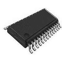
CY8CLED16P01-28PVXIT Cypress Semiconductor Corp, CY8CLED16P01-28PVXIT Datasheet - Page 2

CY8CLED16P01-28PVXIT
Manufacturer Part Number
CY8CLED16P01-28PVXIT
Description
IC PLC PSOC CMOS LED 16CH 28SSOP
Manufacturer
Cypress Semiconductor Corp
Series
PowerPSoC® CY8CLEDr
Datasheet
1.CY8CLED16P01-48LFXI.pdf
(46 pages)
Specifications of CY8CLED16P01-28PVXIT
Package / Case
28-SSOP
Core Processor
M8C
Core Size
8-Bit
Speed
24MHz
Connectivity
I²C, IrDA, SPI, UART/USART
Peripherals
LED, PLC, POR, PWM, WDT
Number Of I /o
24
Program Memory Size
32KB (32K x 8)
Program Memory Type
FLASH
Ram Size
2K x 8
Voltage - Supply (vcc/vdd)
4.75 V ~ 5.25 V
Data Converters
A/D 4x14b; D/A 4x9b
Oscillator Type
Internal
Operating Temperature
-40°C ~ 85°C
Operating Supply Voltage
4.75 V to 5.25 V
Maximum Supply Current
8 mA
Maximum Operating Temperature
+ 85 C
Mounting Style
SMD/SMT
Minimum Operating Temperature
- 40 C
Lead Free Status / RoHS Status
Lead free / RoHS Compliant
Eeprom Size
-
Lead Free Status / Rohs Status
Details
1. PLC Functional Overview
The CY8CLED16P01 is an integrated Powerline Communication
(PLC) chip with the Powerline Modem PHY and Network
Protocol Stack running on the same device. Apart from the PLC
core, the CY8CLED16P01 also offers Cypress's revolutionary
PSoC technology that enables system designers to integrate
multiple functions on the same chip.
1.1 Robust Communication using Cypress’s PLC
Powerlines are available everywhere in the world and are a
widely available communication medium for PLC technology.
The pervasiveness of powerlines also makes it difficult to predict
the characteristics and operation of PLC products. Because of
the variable quality of powerlines around the world, imple-
menting robust communication has been an engineering
challenge for years. The Cypress PLC solution enables secure
and reliable communications. Cypress PLC features that enable
robust communication over powerlines include:
■
■
■
■
1.2 Powerline Modem PHY
Figure 1-1. Physical Layer FSK Modem
The physical layer of the Cypress PLC solution is implemented
using an FSK modem that enables half duplex communication
on any high voltage and low voltage powerline. This modem
supports raw data rates up to 2400 bps. A block diagram is
shown in
Document Number: 001-49263 Rev. *E
Integrated Powerline PHY modem with optimized filters and
amplifiers to work with lossy high voltage and low voltage
powerlines.
Powerline optimized network protocol that supports bidirec-
tional communication with acknowledgement-based signaling.
In case of data packet loss due to bursty noise on the powerline,
the transmitter has the capability to retransmit data.
The Powerline Network Protocol also supports an 8-bit CRC
for error detection and data packet retransmission.
A Carrier Sense Multiple Access (CSMA) scheme is built into
the network protocol that minimizes collisions between packet
transmissions on the powerline and supports multiple masters
and reliable communication on a bigger network.
PLC Core
Network Protocol
Physical Layer
FSK Modem
Solution
Powerline
Figure 1-2.
Powerline Communication Solution
Powerline Transceiver Packet
Embedded Application
PSoC Core
System Resources
MAC, Decimator, I2C,
Additional System
Digital and Analog
Programmable
SPI, UART etc.
Resources
Peripherals
Controller
Communication
PrISM, PWM etc.
HB LED
DALI, DMX512
Technology
Modulation
Additional
Interface
Figure 1-2. Physical Layer FSK Modem Block Diagram
1.2.1 Transmitter Section
Digital data from the network layer is serialized by the digital
transmitter and fed as input to the modulator. The modulator
divides the local oscillator frequency by a definite factor
depending on whether the input data is high level logic ‘1’ or low
level logic ‘0’. It then generates a square wave at 133.3 kHz (logic
‘0’) or 131.8 kHz (logic ‘1’), which is fed to the Programmable
Gain Amplifier to generate FSK modulated signals. This enables
tunable amplification of the signal depending on the noise in the
channel. The logic ‘1’ frequency can also be configured as
130.4 kHz for wider FSK deviation.
1.2.2 Receiver Section
The incoming FSK signal from the powerline is input to a high
frequency (HF) band pass filter that filters out-of-band frequency
components and outputs a filtered signal within the desired
spectrum of 125 kHz to 140 kHz for further demodulation. The
mixer block multiplies the filtered FSK signals with a locally
generated signal to produce heterodyned frequencies.
The intermediate frequency (IF) band pass filters further remove
out-of-band noise as required for further demodulation. This
signal is fed to the correlator, which produces a DC component
(consisting of logic ‘1’ and ‘0’) and a higher frequency
component.
The output of the correlator is fed to a low pass filter (LPF) that
outputs only the demodulated digital data at 2400 baud and
suppresses all other higher frequency components generated in
the correlation process. The output of the LPF is digitized by the
hysteresis comparator. This eliminates the effects of correlator
delay and false logic triggers due to noise. The digital receiver
deserializes this data and outputs to the network layer for inter-
pretation.
Oscillator
Local
Programmable
Gain Amplifier
Transmitter
Modulator
Digital
Square Wave
Frequencies
Logic ‘1’ or
Logic ‘0’
at FSK
Network Protocol
Coupling Circuit
Comparator
Hysteresis
Amplifier
RX
Mixer
Pass Filter
Pass Filter
Correlator
Low Pass
Receiver
HF Band
CY8CLED16P01
IF Band
Digital
Filter
Oscillator
Local
Page 2 of 46
External Low
Pass Filter
[+] Feedback
[+] Feedback


