C8051F301-GMR Silicon Laboratories Inc, C8051F301-GMR Datasheet - Page 27
C8051F301-GMR
Manufacturer Part Number
C8051F301-GMR
Description
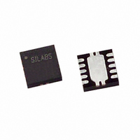
IC 8051 MCU 8K FLASH 11QFN
Manufacturer
Silicon Laboratories Inc
Series
C8051F30xr
Specifications of C8051F301-GMR
Core Processor
8051
Core Size
8-Bit
Speed
25MHz
Connectivity
SMBus (2-Wire/I²C), UART/USART
Peripherals
POR, PWM, WDT
Number Of I /o
8
Program Memory Size
8KB (8K x 8)
Program Memory Type
FLASH
Ram Size
256 x 8
Voltage - Supply (vcc/vdd)
2.7 V ~ 3.6 V
Oscillator Type
Internal
Operating Temperature
-40°C ~ 85°C
Package / Case
11-VQFN
Package
11QFN EP
Device Core
8051
Family Name
C8051F30x
Maximum Speed
25 MHz
Operating Supply Voltage
3.3 V
Data Bus Width
8 Bit
Number Of Programmable I/os
8
Interface Type
I2C/SMBus/UART
Number Of Timers
3
For Use With
336-1444 - ADAPTER PROGRAM TOOLSTICK F300336-1319 - REFERENCE DESIGN STEPPER MOTOR
Lead Free Status / RoHS Status
Lead free / RoHS Compliant
Eeprom Size
-
Data Converters
-
Available stocks
Company
Part Number
Manufacturer
Quantity
Price


4.
N.C. pins for F30x GP packages: 4, 9, 11
CNVSTR
XTAL1 /
XTAL2 /
VREF /
C2CK /
Name
P0.6 /
C2D /
GND
P0.0
P0.1
P0.2
P0.3
P0.4
P0.5
P0.7
RST
V
DD
Pinout and Package Definitions
F300/1/2/3/4/5
GM
Pin
10
11
1
2
3
4
5
6
7
8
9
Table 4.1. Pin Definitions for the C8051F300/1/2/3/4/5
F300/1/2/3/4/5
Pin
GP
10
12
13
14
5
6
7
8
1
2
3
D I/O or
D I/O or
D I/O or
D I/O or
D I/O or
D I/O or
D I/O or
A Out
D I/O
D I/O
D I/O
D I/O
Type
D I/O
A In
A In
A In
A In
A In
A In
A In
A In
A In
Rev. 2.9
External Voltage Reference Input.
Port 0.0. See
Port 0.1. See
Power Supply Voltage.
Crystal Input. This pin is the external oscillator cir-
cuit return for a crystal or ceramic resonator. See
Section
Port 0.2. See
Crystal Input/Output. For an external crystal or res-
onator, this pin is the excitation driver. This pin is
the external clock input for CMOS, capacitor, or RC
network configurations. See
Port 0.3. See
Port 0.4. See
Port 0.5. See
Clock signal for the C2 Development Interface.
Device Reset. Open-drain output of internal POR or
V
tem reset by driving this pin low for at least 10 µs.
Port 0.6. See
ADC External Convert Start Input Strobe.
Data signal for the C2 Development Interface.
Port 0.7. See
Ground.
DD
monitor. An external source can initiate a sys-
11.2.
C8051F300/1/2/3/4/5
Section 12
Section 12
Section 12
Section 12
Section 12
Section 12
Section 12
Section 12
Description
for complete description.
for complete description.
for complete description.
for complete description.
for complete description.
for complete description.
for complete description.
for complete description.
Section
11.2.
27
Related parts for C8051F301-GMR
Image
Part Number
Description
Manufacturer
Datasheet
Request
R

Part Number:
Description:
SMD/C°/SINGLE-ENDED OUTPUT SILICON OSCILLATOR
Manufacturer:
Silicon Laboratories Inc
Part Number:
Description:
Manufacturer:
Silicon Laboratories Inc
Datasheet:
Part Number:
Description:
N/A N/A/SI4010 AES KEYFOB DEMO WITH LCD RX
Manufacturer:
Silicon Laboratories Inc
Datasheet:
Part Number:
Description:
N/A N/A/SI4010 SIMPLIFIED KEY FOB DEMO WITH LED RX
Manufacturer:
Silicon Laboratories Inc
Datasheet:
Part Number:
Description:
N/A/-40 TO 85 OC/EZLINK MODULE; F930/4432 HIGH BAND (REV E/B1)
Manufacturer:
Silicon Laboratories Inc
Part Number:
Description:
EZLink Module; F930/4432 Low Band (rev e/B1)
Manufacturer:
Silicon Laboratories Inc
Part Number:
Description:
I°/4460 10 DBM RADIO TEST CARD 434 MHZ
Manufacturer:
Silicon Laboratories Inc
Part Number:
Description:
I°/4461 14 DBM RADIO TEST CARD 868 MHZ
Manufacturer:
Silicon Laboratories Inc
Part Number:
Description:
I°/4463 20 DBM RFSWITCH RADIO TEST CARD 460 MHZ
Manufacturer:
Silicon Laboratories Inc
Part Number:
Description:
I°/4463 20 DBM RADIO TEST CARD 868 MHZ
Manufacturer:
Silicon Laboratories Inc
Part Number:
Description:
I°/4463 27 DBM RADIO TEST CARD 868 MHZ
Manufacturer:
Silicon Laboratories Inc
Part Number:
Description:
I°/4463 SKYWORKS 30 DBM RADIO TEST CARD 915 MHZ
Manufacturer:
Silicon Laboratories Inc
Part Number:
Description:
N/A N/A/-40 TO 85 OC/4463 RFMD 30 DBM RADIO TEST CARD 915 MHZ
Manufacturer:
Silicon Laboratories Inc
Part Number:
Description:
I°/4463 20 DBM RADIO TEST CARD 169 MHZ
Manufacturer:
Silicon Laboratories Inc