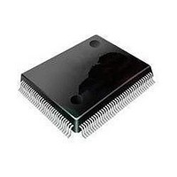
MC9S08DZ128MLL Freescale Semiconductor, MC9S08DZ128MLL Datasheet - Page 2

MC9S08DZ128MLL
Manufacturer Part Number
MC9S08DZ128MLL
Description
MCU 8BIT 128K FLASH 100-LQFP
Manufacturer
Freescale Semiconductor
Series
HCS08r
Datasheets
1.MC9S08DV96CLF.pdf
(458 pages)
2.MC9S08DV96CLF.pdf
(4 pages)
3.MC9S08DZ128CLF.pdf
(4 pages)
Specifications of MC9S08DZ128MLL
Core Processor
HCS08
Core Size
8-Bit
Speed
40MHz
Connectivity
CAN, I²C, LIN, SCI, SPI
Peripherals
LVD, POR, PWM, WDT
Number Of I /o
87
Program Memory Size
128KB (128K x 8)
Program Memory Type
FLASH
Eeprom Size
2K x 8
Ram Size
8K x 8
Voltage - Supply (vcc/vdd)
2.7 V ~ 5.5 V
Data Converters
A/D 24x12b
Oscillator Type
External
Operating Temperature
-40°C ~ 125°C
Package / Case
100-LQFP
Processor Series
S08DZ
Core
HCS08
Data Bus Width
8 bit
Data Ram Size
8 KB
Interface Type
CAN, I2C, SCI, SPI
Maximum Clock Frequency
40 MHz
Number Of Programmable I/os
88
Number Of Timers
3
Operating Supply Voltage
5.5 V
Maximum Operating Temperature
+ 125 C
Mounting Style
SMD/SMT
3rd Party Development Tools
EWS08
Development Tools By Supplier
DEMO9S08DZ60
Minimum Operating Temperature
- 40 C
On-chip Adc
12 bit, 24 Channel
Controller Family/series
HCS08
No. Of I/o's
87
Eeprom Memory Size
2KB
Ram Memory Size
8KB
Cpu Speed
40MHz
No. Of Timers
3
Digital Ic Case Style
LQFP
Rohs Compliant
Yes
Lead Free Status / RoHS Status
Lead free / RoHS Compliant
Available stocks
Company
Part Number
Manufacturer
Quantity
Price
Company:
Part Number:
MC9S08DZ128MLL
Manufacturer:
FREESCAL
Quantity:
300
Company:
Part Number:
MC9S08DZ128MLL
Manufacturer:
Freescale Semiconductor
Quantity:
10 000
SE156-ADC-COCO: COCO bit may not get cleared when ADCSC1 is written to
2
Description:
Workaround:
Errata type:
Affected component:
Description:
In normal 10-bit or 12-bit operation of the ADC, the coherency mechanism
will freeze the conversion data such that when the high byte of data is read,
the low byte of data is frozen, ensuring that the high and low bytes represent
result data from the same conversion.
In the errata case, there is a single-cylce (bus clock) window per conversion
cycle when a high byte may be read on the same cycle that subsequent a
conversion is completing. Although extremely rare due to the precise timing
required, in this case, it is possible that the data transfer occurs, and the low
byte read may be from the most recently completed conversion.
In systems where the ADC is running off the bus clock, and the data is read
immediately upon completion of the conversion, the errata will not occur.
Also, in single conversion mode, if the data is read prior to starting a new
conversion, then the errata will not occur.
The errata does not impact 8-bit operation.
Introducing significant delay between the conversion completion and reading
the data, while a following conversion is executing/pending, could increase
the probability for the errata to occur. Nested interrupts, significant differences
between the bus clock and the ADC clock , and not handling the result register
reads consecutively, can increase the delay and therefore the probability of
the errata occuring.
Using the device in 8-bit mode will eliminate the possibility of the errata
occuring.
Using the ADC in single conversion mode, and reading the data register prior
to initiating a subsequent conversion will eliminate the possibility of the errata
occuring.
Minimizing the delay between conversion complete and processing the data
can minimize the risk of the errata occuring. Disabling interrupts on higher
priority modules and avoiding nested interrupts can reduce possible
contentions that may delay the time from completing a conversion and
handling the data. Additionally, increasing the bus frequency when running
the ADC off the asynchronous clock, may reduce the delay from conversion
complete to handling of the data.
Silicon
ADC
If an ADC conversion is near completion when the ADC Status and Control
1 Register (ADCSC1) is written to (i.e., to change channels), it is possible for
the conversion to complete, setting the COCO bit, before the write instruction
is fully executed. In this scenario, the write may not clear the COCO bit, and
the data in the ADC Result register (ADCR) will be that of the recently
completed conversion.
If interrupts are enabled, then the interrupt vector will be taken immediately
following the write to the ADCSC1 register.
Mask Set Errata for Mask 2M78G, Rev. 0, 7/2008
Freescale Semiconductor


