R5F21334CNFP#U0 Renesas Electronics America, R5F21334CNFP#U0 Datasheet - Page 353
R5F21334CNFP#U0
Manufacturer Part Number
R5F21334CNFP#U0
Description
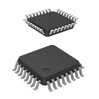
MCU 1KB FLASH 16K ROM 32-LQFP
Manufacturer
Renesas Electronics America
Series
R8C/3x/33Cr
Datasheet
1.R5F21331CNFPU0.pdf
(622 pages)
Specifications of R5F21334CNFP#U0
Core Processor
R8C
Core Size
16/32-Bit
Speed
20MHz
Connectivity
I²C, LIN, SIO, SSU, UART/USART
Peripherals
POR, PWM, Voltage Detect, WDT
Number Of I /o
27
Program Memory Size
16KB (16K x 8)
Program Memory Type
FLASH
Ram Size
1.5K x 8
Voltage - Supply (vcc/vdd)
1.8 V ~ 5.5 V
Data Converters
A/D 12x10b; D/A 2x8b
Oscillator Type
Internal
Operating Temperature
-20°C ~ 85°C
Package / Case
32-LQFP
Lead Free Status / RoHS Status
Lead free / RoHS Compliant
Eeprom Size
-
Available stocks
Company
Part Number
Manufacturer
Quantity
Price

Part Number:
R5F21334CNFP#U0R5F21334CNFP#V2
Manufacturer:
Renesas Electronics America
Quantity:
10 000


R8C/33C Group
REJ09B0570-0100 Rev.1.00 Dec. 14, 2009
Page 323 of 589
Figure 21.8
21.4.1
Table 21.8
i = 0 or 1
Note:
Bit Rate
115200
14400
19200
28800
38400
57600
(bps)
1200
2400
4800
9600
1. For the high-speed on-chip oscillator, the correction value in the FRA4 register should be written into the FRA1
In UART mode, the bit rate is the frequency divided by the UiBRG (i = 0 or 1) register and divided by 16.
register and the correction value in the FRA5 register should be written into the FRA3 register.
This applies when the high-speed on-chip oscillator is selected as the system clock and bits FRA22 to FRA20
in the FRA2 register are set to 000b (divide-by-2 mode). For the precision of the high-speed on-chip oscillator,
refer to 32. Electrical Characteristics.
Source
UiBRG
Count
Bit Rate
f8
f8
f8
f1
f1
f1
f1
f1
f1
f1
Setting value in UiBRG register =
Setting value in UiBRG register =
Bit Rate Setting Example in UART Mode (Internal Clock Selected)
Formula for Calculating Setting Value in UiBRG (i = 0 or 1) Register
UART mode
129 (81h)
129 (81h)
42 (2Ah)
10 (0Ah)
64 (40h)
32 (20h)
86 (56h)
64 (40h)
32 (20h)
21 (15h)
i = 0 or 1
UiBRG
Setting
Value
• Internal clock selected
• External clock selected
System Clock = 20 MHz
Actual Time
113636.36
14367.82
19230.77
29069.77
37878.79
56818.18
(bps)
1201.92
2403.85
4734.85
9615.38
fj: Count source frequency of UiBRG register (f1, f8, f32, or fC)
fEXT: Count source frequency of UiBRG register (external clock)
Setting
Error
(%)
-1.36 29 (1Dh)
-0.22 79 (4Fh)
-1.36 29 (1Dh)
-1.36 19 (13h)
-1.36
0.16 119 (77h)
0.16 59 (3Bh)
0.16 119 (77h)
0.16 59 (3Bh)
0.94 39 (27h)
System Clock = 18.432 MHz
9 (09h)
UiBRG
Setting
Value
Bit Rate × 16
Bit Rate × 16
fEXT
Actual Time
fj
115200.00
14400.00
19200.00
28800.00
38400.00
57600.00
(bps)
1200.00
2400.00
4800.00
9600.00
21. Serial Interface (UARTi (i = 0 or 1))
− 1
− 1
Setting
Error
(%)
0.00 51 (33h)
0.00 25 (19h)
0.00 12 (0Ch)
0.00 51 (33h)
0.00 34 (22h) 14285.71
0.00 25 (19h) 19230.77
0.00 16 (10h) 29411.76
0.00 12 (0Ch) 38461.54
0.00
0.00
(1)
UiBRG
Setting
8 (08h)
Value
System Clock = 8 MHz
−
55555.56
1201.92
2403.85
4807.69
9615.38
Actual
(bps)
Time
−
Setting
Error
(%)
-0.79
-3.55
0.16
0.16
0.16
0.16
0.16
2.12
0.16
−
Related parts for R5F21334CNFP#U0
Image
Part Number
Description
Manufacturer
Datasheet
Request
R

Part Number:
Description:
KIT STARTER FOR M16C/29
Manufacturer:
Renesas Electronics America
Datasheet:

Part Number:
Description:
KIT STARTER FOR R8C/2D
Manufacturer:
Renesas Electronics America
Datasheet:

Part Number:
Description:
R0K33062P STARTER KIT
Manufacturer:
Renesas Electronics America
Datasheet:

Part Number:
Description:
KIT STARTER FOR R8C/23 E8A
Manufacturer:
Renesas Electronics America
Datasheet:

Part Number:
Description:
KIT STARTER FOR R8C/25
Manufacturer:
Renesas Electronics America
Datasheet:

Part Number:
Description:
KIT STARTER H8S2456 SHARPE DSPLY
Manufacturer:
Renesas Electronics America
Datasheet:

Part Number:
Description:
KIT STARTER FOR R8C38C
Manufacturer:
Renesas Electronics America
Datasheet:

Part Number:
Description:
KIT STARTER FOR R8C35C
Manufacturer:
Renesas Electronics America
Datasheet:

Part Number:
Description:
KIT STARTER FOR R8CL3AC+LCD APPS
Manufacturer:
Renesas Electronics America
Datasheet:
Part Number:
Description:
KIT STARTER FOR RX610
Manufacturer:
Renesas Electronics America
Datasheet:

Part Number:
Description:
KIT STARTER FOR R32C/118
Manufacturer:
Renesas Electronics America
Datasheet:

Part Number:
Description:
KIT DEV RSK-R8C/26-29
Manufacturer:
Renesas Electronics America
Datasheet:

Part Number:
Description:
KIT STARTER FOR SH7124
Manufacturer:
Renesas Electronics America
Datasheet:

Part Number:
Description:
KIT STARTER FOR H8SX/1622
Manufacturer:
Renesas Electronics America
Datasheet:

Part Number:
Description:
KIT DEV FOR SH7203
Manufacturer:
Renesas Electronics America
Datasheet: