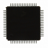
MC9S08DZ60ACLH Freescale Semiconductor, MC9S08DZ60ACLH Datasheet - Page 415

MC9S08DZ60ACLH
Manufacturer Part Number
MC9S08DZ60ACLH
Description
IC MCU 60K FLASH 4K RAM 64-LQFP
Manufacturer
Freescale Semiconductor
Series
HCS08r
Datasheets
1.DEMO9S08DZ60.pdf
(416 pages)
2.EVB9S08DZ60.pdf
(4 pages)
3.MC9S08DZ48AMLF.pdf
(458 pages)
Specifications of MC9S08DZ60ACLH
Core Processor
HCS08
Core Size
8-Bit
Speed
40MHz
Connectivity
CAN, I²C, LIN, SCI, SPI
Peripherals
LVD, POR, PWM, WDT
Number Of I /o
53
Program Memory Size
60KB (60K x 8)
Program Memory Type
FLASH
Eeprom Size
2K x 8
Ram Size
4K x 8
Voltage - Supply (vcc/vdd)
2.7 V ~ 5.5 V
Data Converters
A/D 24x12b
Oscillator Type
External
Operating Temperature
-40°C ~ 85°C
Package / Case
64-LQFP
Processor Series
S08DZ
Core
HCS08
Data Bus Width
8 bit
Data Ram Size
4 KB
Interface Type
CAN, I2C, SCI, SPI
Number Of Programmable I/os
53
Operating Supply Voltage
5.5 V
Mounting Style
SMD/SMT
3rd Party Development Tools
EWS08
Development Tools By Supplier
DEMO9S08DZ60
On-chip Adc
12 bit, 24 channel
Package
64LQFP
For Use With
DEMO9S08DZ60 - BOARD DEMOEVB9S08DZ60 - BOARD EVAL FOR 9S08DZ60
Lead Free Status / RoHS Status
Lead free / RoHS Compliant
Available stocks
Company
Part Number
Manufacturer
Quantity
Price
Company:
Part Number:
MC9S08DZ60ACLH
Manufacturer:
Freescale Semiconductor
Quantity:
10 000
Part Number:
MC9S08DZ60ACLH
Manufacturer:
FREESCALE
Quantity:
20 000
- Current page: 415 of 458
- Download datasheet (5Mb)
1
2
TRGSEL = 0 to select no opcode tracking qualification and TAG = 1 to specify a tag-type CPU breakpoint, the CPU breakpoint would not take
effect until sometime after the FIFO stopped storing values. Depending on program loops or interrupts, the delay could be very long.
3
TRGSEL = 1 to select opcode tracking qualification and TAG = 0 to specify a force-type CPU breakpoint, the CPU breakpoint would erroneously
take effect before the FIFO stopped storing values and the debug run would not complete normally.
4 In begin trace configurations (BEGIN = 1) where a CPU breakpoint is enabled (BRKEN = 1), TAG should not be set to 1. In begin trace debug
runs, the CPU breakpoint corresponds to the FIFO full condition which does not correspond to a taggable instruction fetch.
18.4.5
The FIFO is an eight word deep FIFO. In all trigger modes except for event only, the data stored in the
FIFO will be change of flow addresses. In the event only trigger modes only the data bus value
corresponding to the event is stored. In event only trigger modes, the high byte of the valid data from the
FIFO will always read a 0x00 and the extended information byte in DBGFX will always read 0x00.
18.4.5.1
In all trigger modes except for the event only modes, the address stored in the FIFO will be determined by
the change of flow indicators from the core. The signal core_cof[1] indicates the current core address is
the destination address of an indirect JSR or JMP instruction, or a RTS, RTC, or RTI instruction or interrupt
vector and the destination address should be stored. The signal core_cof[0] indicates that a conditional
branch was taken and that the source address of the conditional branch should be stored.
18.4.5.2
Storing with Begin-Trigger can be used in all trigger modes. Once the DBG module is enabled and armed
in the begin-trigger mode, data is not stored in the FIFO until the trigger condition is met. Once the trigger
condition is met the DBG module will remain armed until 8 words are stored in the FIFO. If the
core_cof[1] signal becomes asserted, the current address is stored in the FIFO. If the core_cof[0] signal
becomes asserted, the address registered during the previous last cycle is decremented by two and stored
in the FIFO.
18.4.5.3
Storing with End-Trigger cannot be used in event-only trigger modes. Once the DBG module is enabled
and armed in the end-trigger mode, data is stored in the FIFO until the trigger condition is met. If the
core_cof[1] signal becomes asserted, the current address is stored in the FIFO. If the core_cof[0] signal
becomes asserted, the address registered during the previous last cycle is decremented by two and stored
in the FIFO. When the trigger condition is met, the ARM and ARMF will be cleared and no more data will
be stored. In non-event only end-trigger modes, if the trigger is at a change of flow address the trigger event
will be stored in the FIFO.
18.4.5.4
The data stored in the FIFO can be read using BDM commands provided the DBG module is enabled and
not armed (DBGEN=1 and ARM=0). The FIFO data is read out first-in-first-out. By reading the CNT bits
Freescale Semiconductor
When BRKEN = 0, TAG is do not care (x in the table).
In end trace configurations (BEGIN = 0) where a CPU breakpoint is enabled (BRKEN = 1), TRGSEL should agree with TAG. In this case, where
In end trace configurations (BEGIN = 0) where a CPU breakpoint is enabled (BRKEN = 1), TRGSEL should agree with TAG. In this case, where
FIFO
Storing Data in FIFO
Storing with Begin-Trigger
Storing with End-Trigger
Reading Data from FIFO
MC9S08DZ128 Series Data Sheet, Rev. 1
Chapter 18 Debug Module (S08DBGV3) (128K)
415
Related parts for MC9S08DZ60ACLH
Image
Part Number
Description
Manufacturer
Datasheet
Request
R
Part Number:
Description:
Manufacturer:
Freescale Semiconductor, Inc
Datasheet:
Part Number:
Description:
Manufacturer:
Freescale Semiconductor, Inc
Datasheet:
Part Number:
Description:
Manufacturer:
Freescale Semiconductor, Inc
Datasheet:
Part Number:
Description:
Manufacturer:
Freescale Semiconductor, Inc
Datasheet:
Part Number:
Description:
Manufacturer:
Freescale Semiconductor, Inc
Datasheet:
Part Number:
Description:
Manufacturer:
Freescale Semiconductor, Inc
Datasheet:
Part Number:
Description:
Manufacturer:
Freescale Semiconductor, Inc
Datasheet:
Part Number:
Description:
Manufacturer:
Freescale Semiconductor, Inc
Datasheet:
Part Number:
Description:
Manufacturer:
Freescale Semiconductor, Inc
Datasheet:
Part Number:
Description:
Manufacturer:
Freescale Semiconductor, Inc
Datasheet:
Part Number:
Description:
Manufacturer:
Freescale Semiconductor, Inc
Datasheet:
Part Number:
Description:
Manufacturer:
Freescale Semiconductor, Inc
Datasheet:
Part Number:
Description:
Manufacturer:
Freescale Semiconductor, Inc
Datasheet:
Part Number:
Description:
Manufacturer:
Freescale Semiconductor, Inc
Datasheet:
Part Number:
Description:
Manufacturer:
Freescale Semiconductor, Inc
Datasheet:


