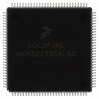
MCF52233CAL60 Freescale Semiconductor, MCF52233CAL60 Datasheet - Page 12

MCF52233CAL60
Manufacturer Part Number
MCF52233CAL60
Description
IC MCU 256K FLASH 60MHZ 112-LQFP
Manufacturer
Freescale Semiconductor
Series
MCF5223xr
Datasheet
1.MCF52236AF50.pdf
(55 pages)
Specifications of MCF52233CAL60
Core Processor
Coldfire V2
Core Size
32-Bit
Speed
60MHz
Connectivity
Ethernet, I²C, SPI, UART/USART
Peripherals
DMA, LVD, POR, PWM, WDT
Number Of I /o
73
Program Memory Size
256KB (256K x 8)
Program Memory Type
FLASH
Ram Size
32K x 8
Voltage - Supply (vcc/vdd)
3 V ~ 3.6 V
Data Converters
A/D 8x12b
Oscillator Type
Internal
Operating Temperature
-40°C ~ 85°C
Package / Case
112-LQFP
Cpu Family
MCF5223x
Device Core
ColdFire
Device Core Size
32b
Frequency (max)
60MHz
Interface Type
I2C/QSPI/UART
Total Internal Ram Size
32KB
# I/os (max)
56
Number Of Timers - General Purpose
10
Operating Supply Voltage (typ)
3.3V
Operating Supply Voltage (max)
3.6V
Operating Supply Voltage (min)
3V
On-chip Adc
8-chx12-bit
Instruction Set Architecture
RISC
Operating Temp Range
-40C to 85C
Operating Temperature Classification
Industrial
Mounting
Surface Mount
Pin Count
112
Package Type
LQFP
Processor Series
MCF522x
Core
ColdFire V2
Data Bus Width
32 bit
Data Ram Size
32 KB
Maximum Clock Frequency
60 MHz
Number Of Programmable I/os
56
Number Of Timers
10
Maximum Operating Temperature
+ 85 C
Mounting Style
SMD/SMT
3rd Party Development Tools
JLINK-CF-BDM26, EWCF
Development Tools By Supplier
M52235EVB, M52233DEMO
Minimum Operating Temperature
- 40 C
Package
112LQFP
Family Name
MCF5223x
Maximum Speed
60 MHz
Operating Supply Voltage
3.3 V
For Use With
M52233DEMO - BOARD DEMO FOR MCF52233
Lead Free Status / RoHS Status
Lead free / RoHS Compliant
Eeprom Size
-
Lead Free Status / Rohs Status
Compliant
Available stocks
Company
Part Number
Manufacturer
Quantity
Price
Company:
Part Number:
MCF52233CAL60
Manufacturer:
FREESCAL
Quantity:
1 000
Company:
Part Number:
MCF52233CAL60
Manufacturer:
Freescale Semiconductor
Quantity:
10 000
MCF52235 Family Configurations
1.2.15
The two periodic interrupt timers (PIT0 and PIT1) are 16-bit timers that provide interrupts at regular intervals with minimal
processor intervention. Each timer can count down from the value written in its PIT modulus register or can be a free-running
down-counter.
1.2.16
The MCF52235 has an 8-channel, 8-bit PWM timer. Each channel has a programmable period and duty cycle as well as a
dedicated counter. Each of the modulators can create independent continuous waveforms with software-selectable duty rates
from 0 to 100%. The PWM outputs have programmable polarity and can be programmed as left-aligned outputs or
center-aligned outputs. For higher period and duty cycle resolution, each pair of adjacent channels ([7:6], [5:4], [3:2], and [1:0])
can be concatenated to form a single 16-bit channel. The module can, therefore, be configured to support 8/0, 6/1, 4/2, 2/3, or
0/4 8-/16-bit channels.
1.2.17
The watchdog timer is a 32-bit timer that facilitates recovery from runaway code. The watchdog counter is a free-running
down-counter that generates a reset on underflow. To prevent a reset, software must periodically restart the countdown.
1.2.18
The clock module contains a crystal oscillator, 8 MHz on-chip relaxation oscillator (OCO), phase-locked loop (PLL), reduced
frequency divider (RFD), low-power divider status/control registers, and control logic. To improve noise immunity, the PLL,
crystal oscillator, and relaxation oscillator have their own power supply inputs: VDDPLL and VSSPLL. All other circuits are
powered by the normal supply pins, VDD and VSS.
1.2.19
There are two interrupt controllers on the MCF52235. These interrupt controllers are organized as seven levels with up to nine
interrupt sources per level. Each interrupt source has a unique interrupt vector, and provide each peripheral with all necessary
interrupts. Each internal interrupt has a programmable level [1-7] and priority within the level. The seven external interrupts
have fixed levels/priorities.
1.2.20
The direct memory access (DMA) controller provides an efficient way to move blocks of data with minimal processor
intervention. It has four channels that allow byte, word, longword, or 16-byte burst line transfers. These transfers are triggered
by software explicitly setting a DCRn[START] bit or by the occurrence of certain UART or DMA timer events.
1.2.21
The reset controller determines the source of reset, asserts the appropriate reset signals to the system, and keeps track of what
caused the last reset. There are seven sources of reset:
12
•
•
•
•
•
•
External reset input
Power-on reset (POR)
Watchdog timer
Phase locked-loop (PLL) loss of lock
PLL loss of clock
Software
Periodic Interrupt Timers (PIT0 and PIT1)
Pulse Width Modulation (PWM) Timers
Software Watchdog Timer
Phase Locked Loop (PLL)
Interrupt Controller (INTC0/INTC1)
DMA Controller
Reset
MCF52235 ColdFire Microcontroller Data Sheet, Rev. 10
Freescale Semiconductor


