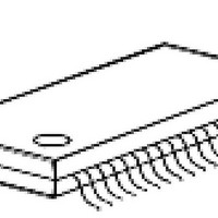
SAA-XC866L-1FRA AB Infineon Technologies, SAA-XC866L-1FRA AB Datasheet - Page 100

SAA-XC866L-1FRA AB
Manufacturer Part Number
SAA-XC866L-1FRA AB
Description
IC MCU 8BIT 4KB FLASH 38TSSOP
Manufacturer
Infineon Technologies
Series
XC8xxr
Datasheet
1.SAA-XC866-1FRA_AB.pdf
(114 pages)
Specifications of SAA-XC866L-1FRA AB
Core Processor
XC800
Core Size
8-Bit
Speed
86MHz
Connectivity
LIN, SSI, UART/USART
Peripherals
Brown-out Detect/Reset, POR, PWM, WDT
Number Of I /o
27
Program Memory Size
4KB (4K x 8)
Program Memory Type
FLASH
Ram Size
768 x 8
Voltage - Supply (vcc/vdd)
2.3 V ~ 5.5 V
Data Converters
A/D 8x10b
Oscillator Type
Internal
Operating Temperature
-40°C ~ 140°C
Package / Case
38-TSSOP
Data Bus Width
8 bit
Data Ram Size
750 B
Interface Type
UART, SSC
Maximum Clock Frequency
26.67 MHz
Number Of Programmable I/os
27
Number Of Timers
3
Operating Supply Voltage
3.3 V, 5 V
Maximum Operating Temperature
+ 85 C
Mounting Style
SMD/SMT
Minimum Operating Temperature
- 40 C
Lead Free Status / RoHS Status
Lead free / RoHS Compliant
Eeprom Size
-
Lead Free Status / Rohs Status
Details
Table 36
Parameter
Overload current
coupling factor for
digital I/O pins
Switched
capacitance at the
reference voltage
input
Switched
capacitance at the
analog voltage
inputs
Input resistance of
the reference input
Input resistance of
the selected analog
channel
1)
2)
3)
4)
5)
Data Sheet
Not subject to production test, verified by design/characterization.
TUE is tested at V
This represents an equivalent switched capacitance. This capacitance is not switched to the reference voltage
at once. Instead of this, smaller capacitances are successively switched to the reference voltage.
The sampling capacity of the conversion C-Network is pre-charged to V
the C-Network. Because of the parasitic elements, the voltage measured at ANx is lower than V
An overload current (
current adds to the respective pin’s leakage current (
overload current and is defined by the overload coupling factor
is inverse compared to the polarity of the overload current that produces it. The total current through a pin is
|
I
TOT
| = |
I
OZ1
| + (|
ADC Characteristics (Operating Conditions apply;
I
AREF
OV
| ×
I
OV
= 5.0 V, V
Symbol
K
C
C
R
R
K
) through a pin injects a certain error current (
AREF
AIN
OVD
AREFSW
AINSW
OV
). The additional error current may distort the input voltage on analog inputs.
CC –
CC –
CC –
CC
CC
AGND
min.
–
–
–
= 0 V , V
Limit Values
DDP
typ .
–
–
10
5
1
1
97
= 5.0 V.
I
OZ
max.
5.0 x
10
1.0 x
10
20
7
2
1.5
). The amount of error current depends on the
-3
-2
K
OV
. The polarity of the injected error current
Unit
–
–
pF
pF
kΩ
kΩ
I
AREF
INJ
) into the adjacent pins. This error
/2 before connecting the input to
Electrical Parameters
Test Conditions/
Remarks
I
I
1)4)
1)5)
1)
1)
OV
OV
V
> 0
< 0
DDP
1)3)
1)3)
SAA-XC866
= 5V Range)
V1.5, 2010-09
AREF
/2.


